For more complete information on 19th Century Military Drill, visit the main page.
THE
HAND-BOOK OF ARTILLERY,
FOR THE
SERVICE OF THE UNITED STATES,
(ARMY AND MILITIA.)
WITH THE
MANUAL OF HEAVY ARTILLERY, INCLUDING
THAT OF THE NEW IRON CARRIAGE.
BY
JOSEPH ROBERTS,
MAJOR 4TH REGT. ART., U. S. A., AND COLONEL 3D PENN. ART.
FIFTH EDITION,
REVISED AND GREATLY ENLARGED.
NEW YORK:
D. VAN NOSTRAND, 192 BROADWAY.
1863

ENTERED, according to Act of Congress, In the year 1863, by
JOSEPHROBERTS,
In the CIerk’s Office of the District Court of the United States for the
Southern District of New York.
JOHN P. TROW
Printed, stereotyped, and electrotyped.
46, 48, & 50 Greene Street,
New York..
The following compilation was prepared for the instruction of non-commissioned officers and privates of the Artillery School, where it was in successful use as a text-book. Much of the matter is taken from Burns’ Questions and Answers on Artillery, Gibbon’s Artillerist’s Manual, Heavy Artillery Tactics, the Ordnance Manual, and Kingsbury’s Artillery and Infantry.
The compiler acknowledges his indebtedness to a work on Ordnance and Gunnery, by Captain Benton, for a portion of the matter on Rifle Cannon.
FORT MONROE, VA., 1863.
_______________
PAGE
PREFACE TO FIFTH EDITION,
. . .
. . .
. . 4
GENERAL TABLE OF CONTENTS,
.
. . 6
PROCEEDINGS, . .
. . . . . .
. . . . . .
. . . 7
PART I. SECTION 1. ARTILLERY INGENERAL,
. . . . 9
”
“ 2. GUNS, . .
. . . .
. . . .
28
“
“ 3. HOWITZERS, .
. . . .
. . . 30
“
“ 4. COLUMBIADS, .
. . . .
. . . 32
“
“ 5. MORTARS,
. . . .
. . . . 33
“ “ 6. SEA-COAST ARTILLERY, . . . . 36
“ “ 7. SIEGE ARTILLERY, . . . . . . 39
“ “ 8. FIELD GUNS AND FIELD BATTERIES, 43
PART II. SECT. 1. POINTING GUNS AND HOWITZERS, 64
2.
POINTING MORTARS, . .
. . 60
PART III. CHARGES,
.
. . .
. .
. . 64
“ IV. RANGES,
. .
. .
. .
. . . 67
“
V. RICOCHET,
. . .
. .
. . . .
. 80
“
VI. RECOIL,
. . . .
. . . .
. . . . 84
“ VII.
WINDAGE, . . .
. . . .
. . . . . 87
“VIII.GUNPOWDER,
. .
. .
. .
. 90
CONTENTS
PAGE
PART IX. PROJECTILES, . . . . . . . 98
“
X. LABORATORY STORES,
.
. .
. 118
“ XI.
PLATFORMS, .
.
.
- .
. 127
“ XIl. ARTILLERY CARRIAGES AND MACHINES, 131
“ XIII. PRACTICAL GUNNERY, . . . . 157
“ XIV. RIFLE CANNON, . . . . . 161
“ IV. MISCELLANEOUS, . . . . . 174
SEQUEL,—SERVING AND WORKING HEAVY ARTILLERY, 187
__________
THE following Report was made by the Committee appointed at a meeting of the staff of the Artillery School at Fort Monroe, Va., to whom the commanding officer of the School had referred this work:
Your Committee to which has been referred the consideration of the work of Captain Roberts, proposed as a textbook for the Artillery Scbool, beg leave to submit the fol- lowing Report, viz:
The work submitted by Captain Roberts, and entitled “Hand-book of Artillery,” embraces sections on the following subjects.
(For subjects see Table of Contents, page 5.)
Under each of these heads, except the last, the work contains a number of questions and answers. Your Committee have carefully examined each of these questions and their corresponding answers, and find that the answers have been principally drawn from the following sources, viz.:
Gibbon’s Artillerist’s Manual, Light and Heavy Artillery Tactics, and the Ordnance Manual, all of which works have been authorized by the War Department. Wherever the
prescribed authorities furnish the means of answering the questions, they appear to have been followed as closely as possible.
In the opinion of your Committee, the arrangement of the subjects and the selection of the several questions and answers have been judicious. The work Is one which, may be advantageously used for reference by the officers, and is admirably adapted to the instruction of non-commissioned officers and privates of Artillery.
Your Committee do therefore recommend that it be substituted as a text-book in place of “Burns’ Questions and Answers on Artillery.”
(Signed) I. VOGDES,
CAPT. 1ST ART’Y.
(Signed) E. 0. C. ORD,
CAPT. 3D ART’Y.
(Signed) J. A. HASKIN,
Bvt. MAJ. AND CAPT. 1ST ART’Y.
The preceding Report
was adopted, and the Staff recommended this work as a book of instruction at
the Artillery
School, in lieu of “Burns’ Questions and Answers on Artillery.”
THE
HAND-BOOK OF ARTILLERY.
_____________
PART I. SECTION I.
1. What is understood by the term ARTILLERY?
Heavy pieces of every description with the implements and materials necessary for their use.
2. how many kinds of pieces are employed in the land service of the United ,States?
Four, viz.: Guns, Howitzers, Columbiads, and Mortars.
3. How are these distinguished?
According to their use, as Sea-coast, Garrison, Siege, and Field Artillery.
4. What metals are used in their construction?
All heavy pieces, such as those for sea-coast, siege, and garrison equipment, are made of iron; and those for field service, of bronze.*
5. What is bronze for cannon?
An ALLOY consisting of 90 parts of copper and 10 of tin, allowing a variation of one part of tin more or less. It is commonly called brass.
* The 3-in rifled filed gun, lately adopted, is made of wrought iron or steel.
HAND-BOOK OF ARTILLERY.
6. Why is bronze used in preference to iron, for field pieces?
This metal, having greater tenacity and strength than iron, the pieces can be made lighter.
7. In what respect does
iron merit a
preference?
Iron is less expensive than bronze, and is more
capable of sustaining long-continued firing with larger charges; such pieces
are, therefore, better calculated for the constant heavy firing of sieges.
NOTE.—In
the sieges In Spain, bronze guns could never support a heavier fire than 120
rounds in twenty-four hours, and were never used to batter at distances
exceeding 300 yards; whereas, with iron guns, three times that number of rounds
were fired with effect, from three times the distance, for several consecutive
days, without any other injury than the enlargement of their vents. The
comparative power of conducting heat in iron and copper being respectively as
3.743 to 8.932, taking gold at 10.000, it is evident that in practising with
iron and bronze pieces of the same calibre, it would soon become necessary to
reduce the charges in the bronze pieces, and, also to increase the time between
the discharges, to prevent their softening and drooping; while with iron, full
charges and rapid firing may be kept up.
8. What additional objection has been urged to bronze for cannon?
The difficulty of forming a perfect alloy, in consequence of the difference of fusibility of tin and copper.
9. What iron pieces are used in the land service?
3-in. (rifled)fieId gun; 41/2-in. (rifled), 12, 18, and 24-pdr. siege and garrison guns; 32 and 42-pdr. sea-coast guns; 8-in, siege and 24-pdr. garrison howitzers; 8 and 10-in, sea-coast howitzers; 8, 10, and 15-in. columbiads; 8 and 10-in.siege, and 10 and 13-in. sea-coast mortars,
ARTILLERY IN GENERAL.
10. What are the kinds of bronze pieces in use at present?
6 and 12.pdr. field guns; 12-pdr. Mountain howitzer; 12, 24, and 32-pdr. field howitzers; and the 24-pdr. Coehorn mortar.
11. What is a battery?
This term is applied to one or more pieces, or the place where they are served.
12. What regulate the dimensions of a piece?
Its calibre and the tenacity and elasticity of’ the metals employed in its fabrication. Its thickness must be pro-portioned to the effect developed by the powder; and the length is determined by experiment, and should not exceed 27 calibres. The exterior surface of a cannon is composed of several surfaces, more or less inclined to the axis of the bore, the forms of which have been determined by experiment.
13. Why is a piece made stronger near the breech than towards the muzzle?
Because the elastic force of the inflamed gun powder is there greatest, constantly diminishing in intensity as the space increases in which it acts.
14. What is the length of a piece?
The distance from the rear of the base-ring to the face of the piece.
15. What is the extreme length?
From the rear of the cascable to the face.
16. What is the BORE of apiece?
It includes the part bored out, viz.: the cylinder, the chamber (if there is one), and the conical or spherical surface connecting them.
17. What is understood by the CALIBRE of a piece
HAND-BOOK OF ARTILLERY.
The diameter of the bore.
18. How do you ascertain
the number of calibers in a piece?
Divide the length of
the cylinder, in inches, by the number of inches in the calibre.
19. The number of calibre, being known, howdo you find the length of the cylinder?
Multiply the number of calibres by the calibre in inches.
20. What is meant by the SIGHTS of a piece?
Artificial marks on the piece for determining the line of fire.
21. How are the sights determined?
Usually by means of the gunner’s level, when the trunnions are perfectly horizontal.
22. What is the LINE OF METAL or the natural line of sight?
A line drawn from the highest point of’ the base-ring to the highest point of the swell of the muzzle, or to the top of the sight, if’ there be one.*
23. What is the axis of apiece?
The central line of the bore.
24. What is the NATURAL ANGLE OF SIGHT?
The angle which the natural line of sight makes with the axis of the piece.
25. What is the DISPART of a piece?
It is the difference of the semi-diameter
of the base-ring and the swell of the muzzle, or the muzzle-band. It is,
therefore, the tangent of the naturalangle of sight to a radius equal to the
distance from the rear of the base-ring to the highest point of the swell of
the muzzle, or the front of the
*The
line of sight nearest the axis of the piece Is the natural line of sight;
the others are artificial lines of sight.
ARTILLERY IN GENERAL.
muzzle-band, — the case may be, measured parallel to the axis.
26. Give the nomenclature of a piece.
The CASCABLE is the projection in rear of the breech, and is composed of the knob, the neck, and the fillet.
The BASE OF THE BREECH is a frustum of’ a cone, or a spherical segment forming the rear surface of the breech.
The BASE-RING* is a projecting band of metal adjoining the base of the breech, and connected with the body of the gun by a concave moulding.
The BREECH is the mass of solid metal behind the bottom of the bore, extending to the cascable.
The REINFORCE is the thickest part of the body of the gun, in front of the breech; if there be more than one reinforce, that which is next the breech is called the first reinforce; the other the second reinforce.
The REINFORCE BAND IS at the junction of the first and second reinforces.
The CHASE is the conical part of the gun in front of the reinforce.
The ASTRAGAL AND FILLETS in field guns, and the chase ring in other pieces, are the mouldings at the front end of the chase.
The NECK is the smallest part of the piece in front of the astragal or the chase ring.
The SWELL OF THE MUZZLE is the largest part of the gun in front of the neck. It is terminated by the muzzle mouldings, which, in field and siege guns,
* This hasdispensed with in the brass 12-pdr. of the new pattern (the NapoIeon gun), and in the new model columbiads. All projections on the surface of cannon which are not required for the service of the piece, have been omitted in the late models.
HAND-BOOK OF ARTILLERY
consist of the lip and fillet. In sea-coast guns and with heavy howitzers and columbiads, there is no fillet. In field and siege howitzers, and in mortars, a muzzle-band takes the place of the swell of the muzzle.
The FACE of the piece is the terminating plane perpendicular to the axis of the bore.
The TRUNNIONS are two cylinders at or near the centre of gravity of a gun, by which it is supported on its carriage. The axes are in a line perpendicular to the axis of the bore, and, in our guns in the same plane with that axis.
The RIMBASEs are short cylinders uniting the trunnions with the body of the gun. The ends of the rimbases, or the shoulders of the trunnions, are planes perpendicular to the axis of the trunnions.
The BORE of the piece includes nil the part bored out, viz. the cylinder, the chamber (if there is one), and the conical or spherical surface connecting them.
The CHAMBER in howitzers, columbiads, and mortars, is the smallest part of the bore, mid contains the charge of powder. In the howitzers and large columbiads,+ the chamber is cylindrical; and is united with the large cylinder of the bore by a conical surface; the angles of intersection of this conical surface with the cylinders of the bore and vent chamber, are rounded (in profile) by arcs of circles. In the siege howitzer, the chamber is united with the cylinder of the bore by a spherical surface, in order that the shell may, when necessary, be inserted without a sabot.
The BOTTOM OF THE BORE (to facilitate sponging) is a plane perpendicular to the axis, united
*By a late order of the War Department, the swell of the muzzle is to be omitted in sea-coast cannon.
+The new columbiad is made without a chamber.
ARTILLERY IN GENERAL
with the sides (in profile) by an arc of a circle the radius of which is one-fourth of the diameter of the bore at the bottom. In the columbiads and the heavy sea-coast mortars, the bottom of the bore is hemispherical.*
The MUZZLE, or mouth of the bore, is chamfered a depth of 0.15 inch to 0.5inch varying with size of the bore), in order to prevent abrasion, and to facilitate loading. The TRUE WINDAGE is the difference between the true diameters of the bore and of the ball.
27. What is the vent?
The aperture through which fire is communicated to the charge.
28. What is to be observed in reference to the diameter of the vent?
It should be as small as the use of the priming wire and tube will allow.
29. Why?
As the velocity of the gases arising from the combustion of the powder is extremely great, a large amount escapes through the vent, which contributes nothing to the velocity of the projectile. It therefore follows, that the effect produced by a given charge will diminish as the diameter of the vent increases. Besides, on account of the increase of power in the current that escapes from them, large vents are more rapidly injured than small ones
30. What is the diameter of the vent?
0.2 of an inch in all pieces.
31. What is the position of the axis of the vent?
* In the late models, the bottom of the bore is a semi-ellipsoid.
HAND-BOOK OF ARTILLERY.
In the old models it is in a plane passing through the axis of the bore, perpendicular to the axis of the trunnions. In guns, and in howitzers having cylindrical chambers, the vent is placed at an angle of 80o with the axis of the bore, and it enters the bore at a distance from the bottom equal to one-fourth the diameter of the bore. The vents of columbiads and mortars of the model of 1881 are in planes parallel to the plane passing through the axis of the bore, and perpendicular to that of the trunnions, and at a distance from it equal to one-half the radius of the bore. The vents are perpendicular to the axis of the bore; the one on the right of the axis is not bored entirely through to the bore by one inch. The vent of the field and siege pieces of the model of 1861 is at right angles to the axis and in the plane passing through it per. vatic perpendicular to that of the trunnions.
32. What are the QUARTER-SIGHTS of a piece?
Divisions marked on the upper quarters of the base ring, commencing where it would be intersected by a plane parallel to the axis of the piece, and tangent to the upper surface of the trunnions.
Note.—Not used In our service.
33. To what use are the quarter-sights applied?
For giving elevations up to three degrees; but especially for pointing a piece at a less elevation than the natural angle of sight.
34. What is a BREECH SIGHT?
An instrument having a graduated scale of tangents, by means of which any elevation may be given to a piece.
35. How are the divisions of the tangent scale found?
ARTILLERY IN GENERAL.
Bytaking the length of the piece, from the rear of the base-ring to the swell of the muzzle, measured on a line parallel to the axis, and multiplying it by the natural tangent of as many degrees as may be required; and then deduct the dispart. Thus, for 50 elevation, and the gun supposed to be 5 feet, or 60 inches long, multiply .08748, which is the natural tangent of 50, by 6O; the product gives 5.2488 inches; supposing the dispart to be 1 inch, the graduating of the tangent scale will be 4.2488 inches.
36. With what pieces are breech-sights used?
Guns and howitzers.
37. What is a PENDULUM IIAUSSE?
It is a tangent-scale, the graduations of which are the tangents of each quarter of a degree of elevation, to a radius equal to the distance between the muzzle-sight of the piece, and the axis of vibration of the hausse, which is one inch in rear of the base-ring. At the lower end of the scale is a brass bulb filled with lead. The slider which marks the divisions on tile scale is of thin brass, and is clamped at any desired division on the scale by means of a screw. The scale passes through a slit in a piece of steel, with which it is connected by a screw, forming a pivot on which the scale can vibrate laterally. This piece of steel terminates in pivots, by means of which the pendulum is sup ported on the seat attached to the gun, and is at liberty to vibrate in the direction of the axis of the piece. The seat is of metal, and is fastened to the base of the breech by screws, so that the centres of the steel pivots of vibration shall be at a distance
ARTILLERY IN GENERAL.
from the axis of the piece equal to the radius of the base-ring.
A MUZZLE-SIGHT of iron is screwed into the swell of the muzzle of guns, or into the middle of the muzzle-ring of howitzers. The height of this sight of a is equal to the dispart of the piece, so that a line joining the muzzle-sight and the pivot of the tangent-scale is parallel to the axis of the piece.
38. What is a GUUNER’S-LEVEL, or gunner’s perpendicular!
An instrument made of sheet-brass; the lower part is cut in the form of a crescent, the points of which are made of steel; a small spirit-level is which fastened to one side of the plate, parallel to the line joining the points of the crescent, and a slider is fastened to the same side of the plate, perpendicular to the axis of the level.
39. What is it used for?
To mark the points of sight on pieces.
40.What is a PLUMMET?
A simple line and bob
for pointing mortars.
41. What is a GUNNER’S QUADRANT?
It is a graduated quarter of a circle of sheet-brass of 6 inches radius, attached to a brass rule 22 inches long. It has an arm carrying a spirit level at its middle, and a vernier at its movable end. To get a required elevation, the vernier is fixed at the indicated degree, the brass rule is then inserted in the bore parallel to the axis of the piece; the gun is then elevated or depressed until the level is horizontal.
There is another graduated quadrant of wood, of 6 inches radius, attached to a rule 23.5 inches long. It has a plumb-line and bob, which are car-
ARTILLERY IN GENERAL.
red, when not in use, in a hole in the end of the rule, covered by a brass plate.
42. What is an ELEVATING ARC, and its use?
It is an arc attached to the rear part of the cheek of a gun-carriage, having its centre in the axis of the trunnions; the arc is graduated into degrees and parts of a degree. By placing the axis of the piece horizontal, and marking the breech at any of the divisions on the arc, any elevation or depression required will be noted by the number of degrees below or above this mark. It turns on a pivot which admits of the arc, when not in use, being placed inside the cheek to which it is attached.
43. What is the use of the cascable?
To facilitate the handling of the piece in mounting and dismounting it, and moving it when off its carrIage.
44. Of what use are the trunnions of a piece? By means of them the piece is attached to its carriage; and by being placed near the centre of gravity, it is easily elevated or depressed.
45. What are the dolphins of a piece?
Two handles* placed upon the piece with their rule centres over the centre of gravity, by which it is mounted or dismounted.
46. Are all pieces provided with dolphins ?
Only the 12-pdr. brass guns, and the 24 and 32-pdr. brass howitzers.
47. What is understood by the preponderance of a piece?
It is the excess of weight of the part in rear of the trunnions over that in front; it is measured by
* In the heavy sea-coast mortars they are replaced by a clevis attached to a projection on the piece.
HAND-BOOK OF ARTILLERY.
the lifting force in pounds, which must be applied at the rear of the base-ring to balance the piece when suspended freely on the axis of the trunnions?
48. Why is this preponderance given?
To prevent the sudden dipping of the muzzle, In firing, and violent concussion on the carriage at the breech.
49. What is bushing a piece of artillery?
Inserting a piece of metal about an inch in diameter (near the bottom of the bore), through the centre of which the vent has been previously drilled. It is screwed in.
50. What kind of metal is used for bushing bronze pieces?
Pure copper always, which is not so liable to run
from heat as gun metal.
51. What is the object of bushing a piece?
To prevent deterioration of the vent, or provide a new one when this has already occurred.
52. Is all new artillery bushed?
No, only rifled and bronze pieces.
53. How are vents replaced?
The vent-piece in bronze and rifled pieces is taken out, and a new one screwed in. In other pieces the vent is filled up by molten zinc, clay being placed on the head of a rammer, and pressed against the upper surface of the bore, so as to close the vent on the interior, and a new one is bored two or three inches from the first.
54. How is artillery rendered unserviceable?
Drive into the vent a jagged and hardened steel spike with a soft point, or a nail without a
*Heavy pieces of the latest models have no “preponderance.”
ARTILLERY IN GENERAL.
head; break it off flush with the outer surface and the point inside by means of the rammer.
II. Wedge a shot in the bottom of the bore by wrapping it with felt, or by means of iron wedges, using the rammer or a bar of iron to drive them in.
Ill. Cause shells to burst in the bore of bronze guns.
IV. Fire broken shot from them with large charges.
V. Fill the piece with sand over the charge, to burst it.
VI. Fire a piece against another, muzzle to muzzle, or the muzzle of one to the chase of the other.
VII. Light a fire under the chase of a bronze gun, and strike on it with a sledge, to bend it.
VIIl. Break off the trunnions of iron guns; or burst them by firing them at a high elevation, with heavy charges and full of shot.
55. State how to unspike a piece.
If the spike is not screwed in or clinched, and the bore is not impeded, put in a charge of powder ½ of the weight of the shot, and ram junk wads over it; laying on the bottom of the bore a slip of wood, with a groove on the under side containing a strand of quick-match, by which fire is communicated to the charge. In a brass gun, take out some of the metal at the upper orifice of the vent, and pour sulphuric acid into the groove, and let it stand some hours before firing. If this method, several times repeated, is not successful, unscrewthe vent piece if it be a brass gun; and if an iron one, drill out the spike, or drill a new vent.
HAND-BOOK OF ARTILLERY.
56. Explain how to drive out a shot wedged in the bore?
Unscrew the vent piece, if there be one, and drive in wedges so as to start the shot forward, then raM it back again in order to seize the wedge with a hook; or pour in powder, and fire it after replacing the vent piece. In the last resort, bore a hole in the bottom of the breech, drive out the shot, and stop the hole with a screw.
Note.- When a shot is jammed is a gun and cannot be rammed home to the cartridge, destroy the charge by pouring water down the vent and muzzle until the ingredients we dissolved, and cleared out of the bore; then introduce a small quantity of powder through the vent, and blow out the shot.
57. Explain how to use a piece which has been spiked?
Insert one end of a piece of quick-match into the cartridge, the other being allowed to project from the muzzle. Apply the fire to the match and get out of the way. When quick-match of sufficient length is not at hand, insert one end in the cartridge, the other projecting in front of the shot, and throw two or three pinches of powder into the bore, after they are rammed home. Place another piece of match in the muzzle, one end projecting out. The fire is applied without danger.
58. What is sealing a piece of artillery?
Flashing off a small quantity of powder to clean out the bore; about 1/12 of the shot’s weight. The practice is discontinued.
59. How are cannon of the old model. in our service marked?
As follows, viz.: The number of the gun and
ARTILLERY IN GENERAL.
the initials of the inspector’s name on the face of muzzle,—the numbers in a separate series for each kind and calibre at each foundry; the initial of the name of the founder, and of the foundry number on the end of the right trunnion; the year of fabrication on the end of the left trunnion; the foundry number on the end of the right rim base, above the trunnion; the weight of the piece in pounds on the base of the breech; the letters U. S. on the upper surface of the piece, near the end of the reinforce.
60. How are the new pieces marked?
As follows, viz.: the number of the gun, the initials of the inspector’s name, and that of the foundry, the year of fabrication, and the weight of the piece in pounds on the face of the piece, in a circle concentric with the bore, in letters and figures at least one inch long; the numbers, in a separate series for each kind and calibre at each foundry; the foundry number, in small figures, on the end of the right rim base, above the trunnion; the letters U. S., in large characters, on the upper surface of the piece, in rear, but near the trunnions.
61. What marks are used to designate condemned pieces?
Pieces rejected on inspection are marked X C on the face of the muzzle; if condemned for erroneous dimensions which cannot be remedied, add X D; if by powder proof, X P.
62. What are the kinds of proof which artillery must undergo, before being received into the service?
1st. They are gauged as to their several dimensions, internal and external; as to justness and position of the bore, the chamber, vent, trunnions, &c.
HAND-BOOK OF ARTILLERY.
2d. They are fired with a regulated charge of powder and shot, being afterwards searched to discover irregularities or holes produced by the firing.
3d. By means of engines, an endeavor is made to force water through them.
4th. They are examined internally, by means of light reflected from a mirror.
63. Are brass cannon liable to external injury, caused by service
They are little subject to such injury, except from the bending of the trunnions sometimes, after long service, or heavy charges.
NOTE.—Recent experiments at Fort Monroe show that brass guns, when rifled, and fired with large charges and heavy shot, expand so much that the projectile does not take the grooves.
64. What are the causes of internal injury?
Internal injuries are caused by the action of the elastic fluids developed in the combustion of the powder, or by the action of the shot in passing out of the bore. These effects generally increase with the calibre of the piece.
65. Name the principal injury of the first kind?
The cutting away of the metal of the upper surface of the bore over the scat of the shot.
86. Name those of the second kind?
The lodgment of the shot,— a compression of the metal on the lower side of the bore, at the seat of the shot, which is caused by the pressure of the gas escaping over the top of the shot. There is a corresponding burr in front of the lodgment; and the motion thereby given to the shot causes it to strike alternately on the top and bottom of the bore, producing other enlargements, generally three
ARTILLERY IN GENERAL.
in number: the first, on the upper side a little in advance of the trunnions; the second, on the lower side about the astragal; the third, in the upper part of the muzzle; it is chiefly from this cause that brass guns become unserviceable. Scratches, caused by the fragments of a broken shot, or the roughness of an imperfect one.
67. When is a piece said to be honeycombed?
When the surface of the bore is full of small holes and cavities.
68. To what is this due?
To the melting and volatilization of a portion of the tin in the alloy; tin being much more fusible than copper.
69. How may the durability of bronze guns be increased?
By careful use, and by the precautions of increasing the length of the cartridge, or that of the sabot, or using a wad over the cartridge, in order to change the place of the shot; by wrapping the shot in woollen or other cloth, or in paper, so as to diminish the windage and the bounding of the shot in the bore. In field guns, both bronze and iron, the paper cap which is taken off the cartridge should always be put over the shot.
70. To what injuries are iron cannon subject?
To the above defects in a less degree than brass, except the corrosion of the metal, by which the vent is rendered unserviceable from enlargement. The principal cause of injury to iron cannon is the rusting of the metal producing a roughness and enlargement of the bore, and increase of any cavities or honeycombs which may exist in the metal.
HAND-BOOK OF ARTILLERY.
71. How may you judge of the service of an iron gun!
Generally by the appearance of the vent. After about 500 rounds the vent, becomes enlarged to 0.3 inch, and should not be used any longer. In rifled guns the wear of the vent is about twice as great as in smooth bore guns.
72. What rules are laid down for the preservation of artillery.
Cannon should be placed together, according to kind and calibre, on skids of stone, iron, or wood, laid on hard ground well rammed and covered with a layer of cinders or of some other material to prevent vegetation. In case of guns and long howitzers, the pieces should rest on the skids in front of the base ring and in rear of the astragal, the axis inclined at an angle of 40 or 50 with the horizon, the muzzle lowest, the trunnions touching each other; or the trunnion of one piece may rest on the adjoining piece, so that the axis of the trunnions may be inclined about 450 to the horizon; the muzzle closed with a tompion or plug of dry wood, well saturated with oil or grease; the vent down, stopped with a greased wooden plug, or with putty or tallow. The pieces may be piled in two tiers, with skids placed between them exactly over those which rest on the ground - the muzzles of both tiers in the same direction and their axes preserving the same inclination. In case of short howitzers and mortars, the pieces should stand on their muzzles, resting on thick planks, the trunnions touching, the vents stopped.
73. What additional precautions should be observed in case of iron pieces?
ARTILLERY IN GENERAL.
They should be covered on the exterior with a lacker impervious to water; the bore and the vent should he greased with a mixture of oil and tallow, or of’ tallow and beeswax melted together and boiled to expel the water. The lacker should be renewed as often as necessary, and the grease at least once a year. The lacker and grease should a applied in hot weather. The cannon should be frequently inspected, to see that moisture does not collect in the bore.
HAND-BOOK OF ARTILLERY
PART I. SECTION II.
I. What are GUNS?
Long cannon without chambers.
2. How are guns denominated!
Smooth bore guns by the weight of their respective shot; and rifled guns by the diameter of the bore in inches. -
3. What are the principal parts of a gun?
The cascable, breech, reinforce, chase and muzzle.
4. What proportion usually exists between the length and calibre of a gun?
It varies from 15 to 27 calibres.
5. What is the natural angle of sight in smooth-bore siege and garrison guns ?
One degree and thirty minutes.
6. What is it in smooth-bore field guns?
One degree in all except the new 12-pdr., in which it is one degree and six minutes.
7. Why have sea-coast guns no natural line of sight?
Because the swell of the muzzle is not visible when the eye is on a level with the base-ring.
NOTE—A natural line of sight may be formed by affixing
a front eight to the muzzle, or to a projection cast on time
piece between the trunnions.
GUNS.
8. Upon what are guns mounted?
On field, siege, barbette orcasemate carriages.
9. What projectiles are used with guns?
Solid shot, shells, spherical-case, grape, and canister.
10. About what are the weights of the different guns?
6-pdr., 884 lbs.; brass 12-pIr., 1,737 lbs., new pattern 1,220 lbs. ; iron 12-pdr., 3,510 lbs., 18-pdr., 4,913 lbs.; 24-pdr., 5,790 lbs.; 32-pdr, 7,200 lbs. ; 42.pdr., 8465lbs. ; 3-in. (rifled) field, 820 lbs.; 44-in. (rifled) siege, 1,450 lbs.
11. Give the entire length of the several guns.
6-pdr. field gun, 65.6 inches; 12-pdr. field gun, 85 inches, new pattern 72.15 inches ; 12-pdr. iron gun, 116 inches ; 18-pdr., 123.25 inches; 24-pdr., 124 inches; 32-pIr., 125.2 inches; 42-pdr., 129 inches ; 3-in. (rifled) field, 73.3 inches; 4-in. (rifled) siege, 133 inches.
HAND-BOOK OF ARTILLERY.
ON HOWITZERS.
I. What is a HOWITZER?
A chambered piece, of larger calibre than a gun of like weight, and mounted in a similar manner.
2. What form of chamber is given to howitzer?
That of a cylinder.
3. How is it united with the large cylinder of the bore?
By a conical surface, except in the 8-inch siege howitzer, where it is united with the cylinder of the bore by a spherical surface, in order that the shell may—when necessary—be inserted without a sabot.
4. What advantages are gained by the employment of howitzers?
They project larger shells than the guns with which they are associated, are well adapted for ricochet fire, the destruction of field works, breaking down palisades, and setting fire to buildings.
5. What projectiles are used with howitzers?
Shells usually, spherical case, canister, grape and carcasses.
6. Give the entire length of the several howitzers?
HOWITZERS.
Iron 10-inch, 124.25 inches; 8-inch sea-coast, 109 inches; 8-inch siege (old), 61.5 inches, (new) 60 inches; 24-pdr. garrison, 69 inches; 32-pdr. field, 82 inches; 24-pdr. field, 71.2 inches; 12-pdr. field, 58.6 inches; mountain, 12-pdr., 37.21 inches.
7. What is the weight of a howitzer of each kind?
10-inch, 9,500 lbs.; 8-inch sea-coast, 5,740 lbs.; 8-inch siege and garrison, 2,614 lbs.; 24-pdr. garrison, 1,476 lbs.; 32.pdr. field, 1,1)20 lbs.; 24-pdr. field, 1,318 his.; 12-pdr. field, 788 lbs.; 12-pdr. mountain, 220 lbs.
8. What is the natural angle of sight in siege and garrison, and field howitzers?
One degree.
9. What in mountain howitzers?
Thirty-seven minutes.
10. Why have sea-coast howitzers no natural line of sight?
Because the swell of the muzzle is not visible when the eye is on a level with the base ring.
11. How are howitzers denominated?
Either by the weight of the solid shot they would carry, or by the diameter of the bore in inches.
HAND-BOOK OF ARTILLERY.
ON COLUMBIADS.
I. What is a COLUMBIAD ?
A gun of much larger calibre than the ordinary gun, used for throwing solid shot, shells, spherical case, or canister.
2. What are some of the peculiarities of this gun, when mounted in barbette?
Its carriage gives a vertical field of fire from 50 depression to 390 elevation; and a horizontal field of fire of 3600.
3. Are these pieces chambered?
Those of the old* pattern have chambers; but they are now made without any.
4. Give the weight of this piece?
OLD PATTERN, 10-inch, 15,400 lbs.; 8-inch, 9,240 lbs. NEW PATTERN, 15-inch, 49,099 lbs.; 10-inch, 15,059 lbs.; 8-inch, 8,465 lbs.
5. What is the entire length of this gun?
OLD PATTERN, 10-inch, 126 inches; 8-inch, 124 inches. NEW PATTERN, 15-inch, 190 inches; 10-inch, 136.6 inches; 8-inch, 119.47 inches.
6. What is the natural angle of sight in this piece?
OLD PATTERN, 8-inch, 10 23’; 10-inch, 10 21’.
NOTE—The great difference between the diameters of the reinforce and muzzle, rendering it impracticable to place an artificial sight on the muzzle, a projection is cast on the upper side of the columbiad, between the trunmons, as a seat for the front sight.
*These are shell guns.
MORTERS.
ON MORTARS.
I. What is a MORTAR?
The shortest piece in service; the trunnions are placed in rear of the vent at the breech; the bore is very large in proportion to the length, and is provided with a chamber.
2. What are the principal advantages obtained By the employment of mortars?
Reaching objects by their vertical fire—such as a town, battery, or other place—whose destruction or injury cannot be effected by direct or ricochet fire; dismounting the enemy’s artillery; setting fire to and overthrowing works; blowing up magazines; breaking through the roofs of barracks, casemates, &c.; and producing havoc and disorder amongst troops.
3. What do you mean by vertical fire?
That produced by firing the mortar at a high elevation:
4. What are its advantages?
The shell having attained a great elevation, descends with great force on the object, in consequence of the constant action of the force of gravity on it.
5. Why are mortars constructed stronger and shorter than other pieces?
HAND-BOOK OF ARTILLERY.
Because greater resistance is required in consequence of the high elevation under which they are fired; and were they longer, the difficulty experienced in loading them would become too great.
6. Why is a mortar constructed with a chamber?
In consequence of employing various charges, some very small, it becomes necessary to use a chamber to concentrate the charge as much as possible, so that the shell may be acted on by the entire expansive force of the powder.
7. What form of chamber is given to mortars I
That of a frustum of a cone. The bottom is hemispherical in the sea-coast mortar. In siege mortars it is a plane surface, the angles of intersection being rounded in profile by arcs of circles.
8. What is this form of chamber called?
Gomer Chamber.
9. What is the advantage of the conical over the cylindrical chamber?
Cylindrical chambers are objectionable, as the projectile is frequently broken in consequence of the small surface exposed to the action of the charge. This defect is obviated by large chambers, and particularly by those that are conical, in which the charge is expended upon nearly a hemisphere.
10. How are mortars designated ?
Usually by the diameter of the bore in inches.
11. How are mortars mounted?
On beds of wood or iron. Those for the new model mortars are made of wrought iron.
MORTARS.
12. What is the
object of mounting mortars on beds in
preference to wheel carriages?
On account of the high elevation at which they are usually fired, when the recoil, instead of forcing the piece backwards, tends to force it downwards, and this tendency becomes so great at the higher angles that no wheel-carriage could long sustain the shock.
13. What is the entire length of each mortar? OLD MODEL, 13.inch, 53 inches; 10-inch sea-coast, 46 inches; 10-inch siege, 28 inches; 8-inch, 22.5 inches; coehorn, 16.32 inches. NEW MODEL, 13-inch, 54.5 inches; 10-inch sea-coast, 47.5 inches; 10-inch siege, 28 inches; 8-inch, 22 inches.
14. What are the weights of mortars?
OLD MODEL, 13-in., 11,500 lbs.; 10-in, sea-coast, 5,775 lbs.; 10-in, siege, 1,852 lbs.; 8-in., 930 lbs.; coeborn, 164 lbs. NEW MODEL, 13-in., 17,120 lbs.; 10-in, sea-coast, 7,300 lbs.; 10-in. siege, 1,900 lbs.: 8-in., 1,010 lbs.
15. What are the weights of the different mortar beds?
8-in, siege, 920 lbs.; 10-in. siege, 1,830 lbs.; cochorn, 132 lbs.
16. What is the diameter of the bore of the coehorn mortar?
5.82inches.
17. What is the length of the bore of the different mortars?
OLD MODEL. 13-in., 39 inches; 10-in. seacoast, 35 inches; 10-in, siege, 20 inches; 8-in., 16 inches; coehorn, 13,07 inches. NEW MODEL, 13-in., 35
HAND-BOOK OF ARTILLERY.
inches; 10-in, sea-coast, 32.5 inches; 10-in. siege, 20.5 inches; 8-in., 10 inches.
18. What is the length of the chamber of. the different mortars?
13-in., 13 inches; 10-in, sea-coast, 10 inches; 10-in, siege, 5 inches; 8-in., 4 inches; coehorn, 425 inches.
19. For what was the eprouvette used?
For determining the relative strength of gunpowder.
20. To what purpose was a stone mortar applied I
To throw stones a short distance, from 150 to 250 yards; and also 6-pr. shells from 50 to 150 yards.
NOTE—The firing of 6 or 12-pdr. shells from mortars of large calibre supersedes the use of the stone mortar. To fire these shells from such mortars we employ a strong tub or half barrel, provided with two strong rope handles, and with two additional bottoms, to the lower of which a block of light, dry wood of the diameter and length of the bore, is nailed, the end of the block next the charge being covered with sheet iron. The fuzes of the shells are cut, driven, uncapped, and the shells placed in tiers in the barrel, the fuzes turned down. The last tier Is covered over with hay, which is rammed to keep the projectile in place. After the charge of powder is put in the mortar, and the proper elevation and direction given, the barrel or tub, loaded, is raised by the handles, the block wiped clean, and introduced into the bore and set home.
21. In what manner were the stones disposed in this mortar?
They were put into a basket fitted to the bore, and placed on a wooden bottom which covers the mouth of the chamber.
MORTARS.
22. What use is made of coehorn mortars?
They are fired either from behind entrenchments like other mortars, or they may accompany troops in effecting lodgments in towns and fortified places.
23. What kind of projectiles are thrown from mortarst
Shells, fire-balls, and carcasses.
24. How rapidly may siege mortars be fired?
At the rate of twelve rounds per hour continuously; and in case of need with greater rapidity.
HAND-BOOK OF ARTILLERY.
SEA-COAST ARTILLERY.
- How are SEA-COAST pieces mounted?
On barbette, casemate, flank casemate, and columbiad carriages; and the carriage upon which the mortar is mounted—called its bed. These carriages do not subserve the purpose of transportation; the barbette wooden carriage may, however, be used for moving its piece for short distances, as from one front of the work to another.
2. What number and kind of pieces are required for the armaments of forts on the seaboard?
In our service they are prescribed by the War Department, according to t e character and extent of the work.
3. What disposition should be made of heavy and light pieces in a fortification?
Heavy pieces should be employed on the salients of the work, or for enfilading channels where a long range is required; light pieces, where the range is shorter.
SIEGE ARTILLERY.
SIEGE ARTILLERY.
1. How are siege-quns mounted?
Usually on travelling-carriages, with limbers.
2. Of what number and kind of pieces is a siege-train composed?
This must altogether depend on circumstances but the following general principles may be observed in assigning the proportion of different kinds and calibres, and the relative quantity of other supplies for a train of 100 pieces:
|
GUNS. |
{ |
24.pdr., about one-half the whole num-ber, . . . . . . 50 18.pdr. or 12-pdr., one-tenth, . 10 |
HOWITZERS. 8-in, siege, one-fourth, . . 25
|
MORTARS. |
{ |
10-in. siege, one-eighth, . . 12 8-in, siege, . . . . . . 3 |
||
|
COEHORN MORTARS. |
{ |
In addition to the 100 pieces, 6
|
||
|
|
|
|
|
|
WALLPIECES, . . . . . . . . 40
CARRIAGES.
For 24-pdr. guns, and 8-in, howitzers, one-fifth
spare, . . . . . . . . . . 90
For 18.pdr. and 12.pdr. guns, . . . . . 12
For 10-in. mortars, one sixth spare, . . . . 21
HANDBOOK OF ARTILLERY.
For 8-in mortars, . . . . . . . . . 4
Mortar-wagons, 1 for each 10-in, mortar and bed,
and for three 8-in, mortars and beds, . . 13
Wagons for transporting implements, in trenching and miner’s tools, laboratory tools and utensil, and other stores each loaded with about 2,700 lbs., say, . . . . . . . . 140
Carts (carrying balls, &c. on the march), . . . 50
Park battery-wagons, fully equipped, . . . . 28
Park forges, . . . . . . . . 8
Sling-carts, large, . . . . . . . . 5
Do. hand, . . . . . . . 4
DRAUGHT H0RSES.
For each. gun and howitzer, with its carriage, . . 8
“ Spare gun-carriage, . . . . . 6
“ Mortar wagon, . . . . . . 8
“ Battery wagon, . . . . . . 6
“ Forge, . . . . . . . 6
“ Cart, . . . . . . . . 2
“ Sling-cart, large, . . . . . . 2
“ Spare horses, . . . . . 1-10th
Total, about 1,900 horses.
PROJECTILES AND AMMUNITION.
|
FOR GUNS. |
{ |
Round-shot, 800 to each 24 pdr.,1,000 to each 18 and 12 pdr. Grape and canisters strapped, 20 rounds to each piece. Spherical-case strapped, 20 rounds to each piece. |
SIEGE ARTILLERY.
|
FOR HOWITZERS. |
{ |
Shells, 800 to each 8-in, howitzer. Canisters strapped, 5 to each. Spher. case strapped. 20 to each |
||
|
FOR MORTARS. |
{ |
600 shells to each 10-inch. 800 “ “ 8-inch. 200 .,. “ “ Coehorn. |
||
|
|
|
|
|
|
Gunpowder, in barrels, 500,000 lbs.
Computing for each 24-pdr. round shot,
one-third
the weight of shot.
“
“
18 and 12 pdr. round shot, one
fourth the weight of shot.
“
“
grape, canister, and spherical-
case, one-sixth the weight of shot.
|
“ “ round of howitzer am’nition,5 lbs. “ “ round 10-in. mortar am’nition,7 lbs. “ “ round 8-in. mortar am’nition,3 lbs. |
} |
including charge of shell. |
“ “ round Coehorn mortar ammunition, ½ lb.
3. WhaI is the best position for guns in order to make a breach?
On the glacis, within 15 or 16 feet of its crest; but if the foot of the revetment cannot be seen from thence, the guns must be placed in the covered way, within 15 feet of the counterscarp.
4. In what manner should the fire of siege-guns be conducted in order to form a breach?
1st. Make a horizontal section the length of the desired breach along the scarp, at one-third its height from the bottom of the ditch, and to a depth equal to the thickness of the wall.
HAND-BOOK OF ARTILLERY.
2d. Make vertical cuts through the wall, not further than ten yards apart, and not exceeding one to each piece of ordnance, beginning at the horizontal section and ascending gradually to the top of the wall.
3d. Fire at the most prominent parts of the masonry left standing; beginning always at the bottom and gradually approaching the top.
4th. Fire into the broken mass with howitzers until the breach is practicable.
5 How long would it take to make a break of 20 yards in length?
Breaches of more than 20 yards in length have been opened by way of experiment, and rendered practicable in less than ten hours, by about two hundred and thirty 24-pdr. balls and forty shells in one case, and by three hundred 18.pdr. balls and forty shells in another.
6. How many discharges can an iron gun sustain?
An iron gun should sustain twelve hundred* discharges, at the rate of twelve an hour; but whatever may be the rate of fire, it is deemed unsafe after that number of discharges. As many as twenty an hour have been made for sixteen consecutive hours.
*Recent experiments at Fort Monroe, Va., prove this to be a safe estimate of the number of discharges an iron gun can sustain as two new model 10-in. columbiads have been fired, with charges of 14 and 15 lbs. of powder, nearly 4000 times each. One of them pieces was mat bellow and the other mild under the direction of captain Rodman of the Ordnance. In consequence of the action of the elastic force of the piece, due to the combustion of the powder. In enlarging the vent, the sieges have had new vents bored in them some 7 or 8 times.
FIELD-GUNS AND BATTERIES.
ON FIELD-GUNS AND BATTERIES.
1. What proportion of artillery should be allotted to an army in the field!
The proportion of artillery to other troops varies generally between the limits of one and three pieces to 1,000 men, according to the strength of the army, the character of the troops composing it, the strength and character of the enemy, the nature of the country which is to be the theatre of the war, and the character and objects of the war.
2. What regulates the selection of the kinds of artillery and the proportion of the different kinds in the train?
Similar considerations to those specified in the foregoing answer. The following principles may be observed in ordinary cases:
|
3 pieces to 1,000 men. |
{ |
2/3 guns, of which 1/3howitz., of which |
|
3. What is a field-battery?
A certain number of pieces of artillery so equipped as to be available for attack or defence, and capable of accompanying cavalry or infantry in ail their movements in the field.
4. How many pieces are allotted to a field-battery?
HAND-BOOK OF ARTILLERY.
Four guns and two howitzers.
5. Are all field.batteriea alike?
No; field-batteries accompanying infantry are composed of the heavier, and those accompanying cavalry of the lighter pieces, the first manned by foot-artillery, and the latter by horse-artillery.
8. In what respect does a battery of horse artillery differ from one of foot artillery!?
The main difference consists in the cannoneers in a battery of horse-artillery being mounted; in rapid evolutions of foot-artillery they are conveyed on the carriages.
7. What is the composition of a field-battery on the war establishment?
KIND OF BATTERY. 12-PR. 6-PR.
|
GUNS. |
{ |
12:pdrs., mounted....…4 6-pdrs., “ ………………..2 |
|
HOWITZERS |
{ |
24-pdrs., mounted…….2 12-pdrs., “ ………………..2 6 6 |
|
CAISSONS |
{ |
For guns………………….8…….….4 For howitzers…………..4 2 12 6 |
TRAVELLING FORGES………………………..1
1
BATERRY WAGON
S…………………………...1
1
2
3
Whole No. of carriages with a battery. 20 14
Ammunition
|
For 4 guns,
For 2 howit
|
|
560 400 224 320 112 80 896 800 168 120 112 160 42 32 322 312 |
Total No. rounds with a battery, 1218 1112
FIELD-GUNS AND BATTERIES.
KIND 0F BATTERY. 12-PR. 6-PR
|
Draught Horses |
{ |
6 to each carriage, 120 84 spare horses, 1-12, 10 7 |
Total………………….. 130 91
|
NOTE—For two 32-pdr. howitzer car riages and four caissons, the number of rounds of ammunition is |
} |
Shells…………………112 Spber. case……………84 Canisters………………14 |
Total………………………………… 210
8. What is the composition of a battery of mountain howitzers!
Howitzers, . . . . . . . . 6
Gun-carriages, . . . . . . . 7
Ammunition-chests, . . . . . . 30
(48 rounds for each howitzer)
Forge and tools, in 2 chests, . . . . 1
Set of carriage-makers’ tools in 2 chests, . . 1
Pack saddles and harness, . . . . 33
Horses or mules, . . . . . . 33
9. What composes the FIELD-PARK?
The spare carriages, reserved supplies of ammunition, tools, and materials for extensive repair; and for making up ammunition, for the service of an army in the field, form the Field-Park, to which should be attached also the batteries of reserve.
10. What determines the quantity of such supplies!
It must depend in a great measure on the particular circumstances of the campaign.
11. How is the ammunition which cannot be transported by the batteries carried?
With the park; in caissons, or in store-wagons.
12. Do any other carriages and stores form part of the Field-Park?
HAND-BOOK OF ARTILLERY.
Yes; spare gun-carriages, one to each field-battery,
|
Travelling Forges, Battery- Wagons, |
} |
one or more of each |
||||
|
Spare spokes, 50 to each battery, Spare Jellies, 20 to each battery,
|
} |
in store wagons |
||||
|
|
|
|
|
|||
Gunpowder, saltpetre, sulphur, charcoal, laboratory paper, percussion-caps for small arms, friction primers for cannon, stuff for cartridge bags, woollen yarn, cotton yarn, glue.
13. Are any other pieces ever used for field service!
Yes: sometimes the 12 and 18-pdr. siege guns, and the 8-in. siege howitzer.
14. For what particular service are these different pieces most suitable?
The siege pieces for batteries of position; the 12-pdr. battery, for following the movements of infantry, and the 6-pdr. battery for those of cavalry.
NOTE.—These siege pieces should be placed on the weakest points of a line, and on heights which either form a key to the position, or from whence the greatest and longest continued effect may be produced.
15. What are the peculiar advantages of Horse Artillery!
Possessing, from their lighter construction and mounted detachments, much greater locomotive powers than other field-batteries, they are especially adapted for following the rapid evolutions of cavalry, for sudden attacks upon particular points, and for supporting the advance or covering the retreat of an army.
FIELD-GUNS AND BATTERIES.
16. How is a field gun mounted?
Upon a four-wheel carriage, which answers for its transportation as well as for its service, similar to a siege carriage, but lighter, and the limber carrying an ammunition chest.
17. Where should a battery be placed before the commencement of an action?
As much as possible under cover, by taking advantage of banks, hollow-ways, buildings, woods, &e.
18. Is it advisable to move a battery at once into action in the field?
No; but if unavoidable, it should be masked as much as possible until ordered to open its fire.
19. How should a battery lie masked?
It practicable, by covering it with cavalry, in preference to infantry, as the former does it more effectually, and is sooner moved out of the way.
20. In commencing an action, how should the of a battery be directed?
When the enemy is in line, the fire should be directed over the whole line, and not upon the real points of attack; but when in column, ready to advance, it should be concentrated upon the real points of attack.
21. How should batteries be placed in relation to the troops with which they are acting?
Upon the flanks of a line, but at such a distance as not to impede its movements, and at the same time to be unfettered in their own; the artillery may thus represent the faces of a bastion, and the line of troops the curtain.
22. Is the front of a line of troops an advantageous position for a field-battery?
On the contrary, it is the worst possible, as
HAND-BOOK OF ARTILLERY.
offering a double object to the enemy’s fire, and greatly obstructing the movements of the troops; while a position in rear is nearly as bad, as the fire might seriously injure, or at learnt, greatly disquiet them.
23. In supporting an attack, what precautions are necessary?
The battery should be carefully kept clear of the Intended line of march of our own troops, and such points occupied as may afford the greatest annoyance to the enemy.
24. How should batteries be disposed with regard to the enemy’s troops?
Generally so as to secure a cross fire on his position, and on all the ground over which he moves to the attack, endeavoring to take him at all times In the direction of his greatest dimensions; that is, obliquely or in flank when in line, and in front when formed in columns. Moderate heights, commanding as much as possible the surrounding country, should always be taken advantage of, but not such as may prevent operations in advance if required.
25. Is it imperatively necessary to confine positions for field-batteries to the flanks of a line?
When, from particular circumstances, the front of the army is too extended, and unavoidably divided into two lines, it may become necessary to place one or more batteries in the centre, if those on the flanks are unable to sweep the whole front; but great care must be taken not to impede the advance or retreat of the troops when required.
28. Should the fire of field-batteries be carried n at the same uniform rate?
Certainly not; the destruction of the enemy be-
FIELD GUNS AND BATTERIES.
ing the object, it follows that at distant ranges, a greater degree of care hi required in pointing the suns; the fire is slow and steady, and increasing in rapidity as the enemy advances, without however impairing its precision.
27. Should the fire of field-batteries be carried on in salvoes or otherwise ?
Never in salvoes; but in a regular manner, well sustained, and with distinct intervals between every round, commencing slowly, and increasing in rapidity as the range diminishes.
28. Is the fire of batteries more efficacious when dispersed than when concentrated?
The effects of the fire will be in proportion to the number of guns brought together, and therefore, in order to strike a decisive blow, this should at once be done.
29. What projectiles are used with field guns?
Solid shot, spherical case, and canister.
30. At what distance from the enemy should the several kinds of projectiles be employed with field battery pieces?
Solid shot from 350 yards and upwards; spherical case from 600 up to 1000 yards, although It may be used within the first range; and canister within 350 yards, or up to 400 against extended formations.
31. What number of rounds can be fired from a field gun in one minute?
Two solid shot or spherical case, or three of canister.
32. Why are more rounds of canister fired in a minute than of solid shot or spherical case!
Because the latter are fired at greater distances
HAND-BOOK OF ARTILLERY.
than canister, and require the piece to be carefully shined, thus requiring more time.
33. What is the smallest number of guns that may with safety be employed in the face of an enemy?
Never less than two, in order to secure a continuous fire and mutual support.
34. Is the practice of employing field-batteries against those of the enemy recommended?
Only under peculiar circumstances; as for instance, when his troops are well covered and his guns exposed, or their fire very destructive.
Their fire should be directed principally against columns of attack, and masses, or upon positions which are intended to be carried.
85. In what time could a battery come into action into action in the field?
It could come into action and fire one round in 26 seconds, timing from the order “action front,” to the discharge of one piece.
38. Suppose cavalry to be advancing to attack infantry, and first observed at the distance of a mile, passing over the first half mile at a trot; the next quarter of a mile at the maneuvring gallop, and the remaining distance at an increased gallop, terminating with the charge; occupying altogether about six minutes: during the last 1500 yards of their advance how many rounds per piece might a battery fire in that time!
Eleven rounds with effect, thus:
From 1500 to 650 yards . . . . . . . . 8’ 32”—spherical-case.. .7
“ 650 to 350 . . . . . . . . . . . . . 0’ 48”—solid shot . . . . . 2
“ 350 to close quarters.... . . 0’ 84”—canister . . . . . . 2
37. What number of rounds could a battery
field guns and batteries.
fire against infantry, supposing them to pass over 1500 yards in about 16 ¼ minutes!
Thirty-six rounds with effect, viz.:
From 1500 to 650....quick step...9’
45”—.spher. case 19
“ 650 to
350
“ 8’ 50”—sold
shot . . . . . 7
“ 350 to
100
“ 2’
5”—canister . . . 8
|
“ 100 to close, quarters. |
{ |
double quick and the charge. |
} |
0’ 40” - can. 2 |
38. Should the enemy attempt to force the passage of a river, what is the best position for artillery to oppose it?
Wherever the best cross fire can be obtained order to obstruct and harass him as much as possible; and if he has succeeded in passing over portion, of his troops, it should be directed against their formation.
39.When the enemy is making the passage of a river in retreat, where should your guns be posted
In such a position as to bear upon the batteries that cover the retreat, and also upon his bridges.
40. In forcing the passage of a river what is most advantageous position for artillery?
The bridge being generally laid in a re-entering angle, batteries should be posted on each side of bridge, and far enough from it to secure a cross-fire on the opposite bank.
41. Should the indiscriminate expenditure of ammunition be permitted in the field during action?
Upon no account; ammunition should at all times be carefully husbanded, particularly at the commencement of an action, as the want of it at the close may decide the fate of the day; it should also be sparingly used in skirmishes and minor
HAND BOOK OF ARTILLERY.
affairs, especially when at a distance from supplies, or in anticipation of a general action.
42. When should the reserve be employed!
When a particular point of the line requires additional support, a favorable position is to be seized, an impression has been made on the line by the enemy, a forward or retrograde movement is in contemplation, or when a determined attack is to be made on him, then the reserve should came up and take part in the action; and it is of the utmost importance that this should be done as expeditiously as circumstances will permit.
48. Where should the reserve be placed previous to an engagement!\?
In rear with the second line, out of the range of shot, and as little exposed as circumstances will admit, but always in such a position as to have ready access to the front or rear.
44. Should guns be lightly abandoned before an enemy?
Never until the VERY LAST EXTREMITY. An artillery-man must never forget that his gun is his proper ARM; that here lies his strength; that here is his post of honor and of duty; also, that the LAST DISCHARGES are always THE MOST DESTRUCTIVE, and MAY POSSIBLY INSURE THE SAFETY OF THE WHOLE ARMY, OR TURN THE TIDE OF VICTORY IN THEIR FAVOR.
45. What is the position for cavalry when placed in support of a battery?
On its flank, about the distance of 100 yards, and as much concealed as possible.
46. What is the proper position of field-Batteries when infantry squares are attacked by cavalry!
FIELD-GUNS AND BATTERIES.
When infantry are formed in squares to resist the charge of cavalry, the guns should be placed inside at the angles of the squares, the limbers, horses, &c., inside. Should the detachments be driven from their guns, they will retire into the square, after discharging their pieces, and taking with them the sponges and other equipments; the moment the enemy has retired, they recommence theirfire. Supposing the infantry formed in echelon of regimental squares, and that the time, or small extent of the squares, would not admit of limbers, &c., being placed inside, then the guns and limbers should be brought up with their broadsides to the front, so as to occupy, if possible, the space between the guns, leaving no intervals for the cavalry to cut through: the prolonge or drag ropes might also offer an effectual momentary impediment to them, if properly stretched and secured.
HAND-BOOK OF ARTILLERY.
POINTING GUNS AND HOWITZERS.
I. What is meant by the term POINTING a piece?
To point a piece, is to give it such a direction and elevation, or depression, that the allot may strike the object; and the rule (except in case of mortars) is: First give the direction and then the elevation, or depression.
2. When a shot is fired from a piece, by how many forces is it acted on?
By three.—1st. The impulsive force of the powder, which urges it forward.
2d. The resistance of the air, which tends to stop it.
3d. The force of gravity, which causes it to descend.
3. Why is it necessary to give a certain degree of elevation to a piece?
Because a shot describes under the action of the above forces a curve called a trajectory, which is situated below the prolongation of the axis of the piece, the extent of its departure from this line increasing with the time of flight. Therefore, the more distant the object, the greater must be the elevation to enable the shot to reach it.
4. How is the direction given to a gun or howitzer?
By directing the line of metal upon the object.
POINTING GUNS AND HOWITZERS.
5. How is the elevation or depression given?
The elevation or depression, which depends upon the charge, the distance, and the position of the object above or below the battery, must be ascertained from tables or by experiment, and the proper degree given by means of instruments.
6. When will the object be struck by merely directing the line of metal upon it?
But in one case—when it is at point-blank distance.’
7. How must the line of metal be directed for all ranges less than the point-blank range, in order to strike it?
So as to pass below the object.
8. Give a simple rule for firing at objects within point-blank.
Add to the point-blank range the difference between it and the required range, set the scale to the elevation corresponding to this sum, as shown by tables of faring. Then aim the gun directly at the object; now apply the scale, and observe where the visual ray of the scale strikes the ground, and having noted this point, aim the gun directly at it.
9. How must the line of metal be directed for ranges greater than the point-blank range, in order to strike it?
Above it.
10. When the line of metal passes over the object, what instruments must be employed for giving the proper elevation?
The gunner’s quadrant, or the breech-sight..
11. How is the quadrant used?
After the direction has been given, the quadrant
HAND-BOOK OF ARTILLERY.
is applied, either by its longer branch to the face of the piece, or this branch is run into the bore parallel with the axis, or it may be applied to the upper surface of the lock-piece, making the allowance due to its inclination with the axis of the piece, which ought to be previously determined, and the elevating screw turned, or the quoin adjusted, until the required degree is indicated.
12. How is the breech-sight used?
It is first set to the elevation corresponding to the distance; it is then applied to the highest point of metal on the base-ring, and by the elevating screw, or quoin, the notch of the breech-sight, the highest point on the swell of the muzzle, and the object, arc brought in the same line.
13. What is a line thus determined called?
An artificial line of sight.
14. In the absence of instruments, how may the elevation be given?
By placing one or more fingers of the left hand upon the base-ring, perpendicular to the axis, and using them as a breech-sIght.
NOTE.—In practice, it is well to fire two or three shots to determine the range experimentally, as it is affected by divers causes.
15. Should the line of metal be always directed in the vertical plane passing through the object?
No; as in practice there are circumstances (as, for instance, a strong wind blowing across the field of fire) which will cause a ball to deviate from this plane, it follows that to strike the object, in such a cane, the line of metal must be directed to its right or left; the gunner judging of the distance by observing the striking of the shot.
POINTING GUNS AND HOWITZERS
NOTE.—The excentricity of a spherical projectile causes it to deviate. If the shot be so placed in the bore that its centre of gravity be to the right of the axis, the deviation will be to the right; if to the left of the axis, the deviation will be to the left; if placed above, the range will be increased, and If below, diminished. The rotation of the earth on its axis is another cause, arising from the fact that points of the earth’s surface not in the same parallel of latitude have different rotary velocities, and that a projectile carries with it the velocity of the point of departure. It is found that a projectile, from this cause, will deviate to the right, in the northern hemisphere, no matter in what direction it is fired, the distance depending on the latitude of the place, and on the range and time of flight. A 12-inch shell of 200 lbs. weight, fired under an angle of 450 and having an initial velocity of 900 feet, will deviate 15 to 20 feet to the right of the object.
16. Is the line of metal a permanent line under all circumstances?
No; in batteries for garrison and sea-coast defence, where the platforms are fixed, the line of metal may be considered as nearly permanent; but with siege guns, which are mounted on travelling carriages, the wheels of which arc liable to vary in position from unevenness of ground, or unequal settling in newly constructed platforms, this line is constantly changing. It approximates the higher wheel in proportion to the difference of level between the wheels; and hence, to secure the greatest accuracy of fire, it must be frequently verified; the old marks, if not found correct, should be erased and new ones substituted.
17. When the notches or sights, which are sometimes made upon the base-ring and swell of the muzzle in field guns, for aiming the piece are used, how is the error of direction remedied when the wheels are not in the same level?
HANDBOOK OF ARTILLERY.
The piece must be aimed more or less to that side which corresponds to the higher wheel, according to the inclination.
18. When the elevation or depression has once been ascertained for any given distance, how may the firing at that distance be facilitated?
By noting some point on the elevating screw or quoin; adjusting some fixed measurement from a point on the stock to another point on the under side of the breech; or by a chalk mark drawn across the face of a trunnion and its corresponding cheek.
19. When firing either within or beyond point-blank range, may remarkable points on the ground be taken advantage of, in order to furnish an object to aim at?
Yes; some fixed object may often p resent itself which will serve as a point upon which to direct the line of metal. No means should be neglected that may tend to secure accuracy of aim; fort he shot that is thrown away by carelessness in pointing, had better not be thrown at all.
20. How may precision of fire be secured at sight?
When a fixed object is to be fired at by night, the piece should be directed during the day, and two narrow and well-dressed strips* of wood laid on the inside of the wheels, and two others outside of the trail of a siege carriage, and nailed or screwed to the platform. In case of a barbette carriage, the traverse wheels should be chocked in the proper
* To prevent injury to the strip from the recoil they should be nailed at such a distance from the carriage that the apace can be filled up with a strip that can be removed before firing.
POINTING GUNS AND HOWITZERS.
position. To preserve the elevation, measure the height of the elevating screw above its box, or take the measure between a point on the gun, and another on the stock; cut a stick to this length and adjust the gun on it at each Fire.
21. Should night-firing with GUNS be limited?
Yes; it should be limited to a small number of rounds, as it consumes ammunition to little advantage.
HAND-BOOK OF ARTILLERY.
POINTING MORTARS.
1. What is the rule for pointing mortars?
First give the elevation, and then the direction.
2. How is the elevation given?
By applying the quadrant to the face of the piece, and adjusting the quoin until the required number of degrees is indicated.
3. Are the same means employed for giving mortars their direction as those which are used with guns and howitzers?
No; because mortars are usually masked from the object to be struck, by an epaulment or parapet.
4. To what are all the methods employed for giving the direction to mortars reduced?
To determining practically two fixed points, which shall be in line with the piece and the object, and sufficiently near to be readily distinguished by the eye. These points being covered by the plummet, determine a vertical plane, which, when including the line of metal, becomes the plane of fire.
5. What is the simplest manner of directing the mortar?
By means of pointing-wires.
POINTING MORTARS.
6. Describe this method?
The two fixed points required are determined by planting two wires upon the epaulment, one upon its crest, and the other about a yard in advance of it, both as nearly as possible in the vertical plane passing through the centre of the platform and the object. The points being thus established, the direction is given to the mortar, by causing a plummet held in rear of it, to cover the wires and the line of metal.
7. In what respects is this method defective ?
Both in accuracy of aim, and the liability of the wires being deranged by the shots of the enemy or by other causes.
8. Give a better method.
By means of pointing-stakes, by which one of the fixed points is established upon the crest of the parapet or at the foot of the interior slope, and another in rear of the piece. Then by a cord called the pointing-cord, stretched between these two points, with the plummet suspended from it, a vertical plane is determined with which the line of metal is made to coincide.
9. How are the stakes planted?
A stake, a foot or more in length, is driven into the crest of the epaulment, as nearly as practicable in the vertical plane of fire passing through the centre of the platform; sighting by this stake, another long one is planted, three or four feet in front of it, in line with the object. To this stake the cord is temporarily attached, and stretched by the first stake, just grazing it, to a point on the ground, one yard in rear of the platform. At this point a third stake is driven. The cord is removed from
![]()
HAND-BOOK OF ARTILLERY.
the second stake, which may now be taken away, and permanently attached to the first.
10. How is the mortar directed?
The cord is stretched to the rear stake, and as near the muzzle band as possible, with the left hand, while the plummet Is suspended against it with the right; or the plummet may be attached to the cord, just in rear of the mortar. The line of metal is then brought into the plane of these two lines.
11. How does it appear that the mortar is thus PROPERLY directed ?
Because the cord, the plummet, and the line of metal, are evidently in the vertical plane of fire.
12. What is done in case the shell should strike constantly to the right or left of the object?
The pointing cord is shifted to some notch on the pointing board, to the right or left, until the shell falls at the desired point.
13. Describe the pointing board.
This is a piece of wood one foot long, two or three inches wide, and one inch thick, having a notch cut in the middle of one side, to fit on the stake and which Is graduated into equal divisions from it~ middle. When not in use, the pointing cord may be wound on it.
14. Describe another mode of planting the POINTING-STAKES.
The mortar being placed upon the middle of the platform, the gunner mounts upon it, and suspend the plummet in front of the muzzle, covering the object. Where the plummet thus suspended cuts the crest of the epaulment, the first stake is driven. A second stake is then driven in the same line be-
POINTING MORTARS.
tween the mortar and the epaulment. The pointing cord being attached to the first stake and stretched to the rear, over the point where the plummet touches the top of the mortar, determines the point on the ground at which the rear stake is driven. The first stake is then removed, and the cord attached permanently to the second stake.
When the object cannot be seen from the mortar, owing to the interposition of some obstacle, as a parapet or a hill, two persons in sight of each other, one of whom faces the mortar, snd the other the object, must by successive changes of position, place themselves in the vertical plane of fire, and at the points thus determined, stakes must be driven, one of which will serve as the object.
15. How may precision of fire be secured at night with mortars?
The direction is preserved by nailing or screwing two boards to the platform outside of the cheeks; the elevation is marked on the quoin, or the quoin may be nailed in the proper position, or a cleat may be nailed to the bolster.
HANDBOOK OF ARTILLERY.
CHARGES.
1. What is the charge of a piece of artillery?
The powder with which it is loaded.
2. What is the ordinary service charge of powder for heavy guns?
One-fourth the weight of the shot.
3. What is it for firing DOUBLE shot?
One-sixth the weight of one shot.
4. What is the breaching charge?
One-third the weight of the shot.
5. What kind of charges are used in hot shot firing?
Small charges from one-fourth to one-sixth the weight of the ball.
6. For what reason?
Because balls fired with small velocities split the wood in a manner which is favorable to its burning;with a great velocity the hole closes, the ball sinks deep, and, deprived of air, chars without setting fire to the surrounding wood.
7. To what depth should hot shot penetrate?
Not deeper than ten or twelve inches.
8. In ricochet firing, what kind of charges are used?
Light charges generally ; varying from two-thirds to one-eighth of the ordinary charge.
CHARGES.
9. In what manner are the charges of mortars regulated?
The charges vary with the elevation; or if the elevation be fixed at any particular angle, they must be determined by the range.
10. What are the chargeS for field guns and field howitzers?
See Table, page 66.
11.What are the charges for heavy guns, columbiads, and howitzers?
See Table, page (16.
12. What are the greatest charges of the seacoast, siege, and coehorn mortars?
See Table, page 66.
13. What charge is used for projecting fire balls from mortars?
One twenty-fifth the weight of the ball.
HAND-BOOK 0F ARTILLERY.
CHARGES FOR FIELD GUNS AND FIELD HOWITZERS.
|
KIND.
|
FOR
GUNS. pr pr |
FOR HOWITZERS. 32 24 12 MTN pr pr pr |
||||
|
For shot... For shells |
lbs. |
lbs. |
lbs. 3.25 |
lbs. 2.5 |
lbs. 1.25 |
lbs. 0.5 |
|
|
|
|
|
|
|
|
CHARGES FOR HEAVY GUNS, COLUMBIADS, AND
HOWITZERS.
|
GUNS. |
COLUMBIADS.*1844
|
HOWITZERS. |
||||||||
|
42 pr |
32 pr |
24 pr |
18 pr |
12 pr |
10 inch |
8 inch |
Siege8-in. |
24 pr Garri-son |
SEA-COAST.
|
|
|
lbs. |
lbs. |
lbs. |
lbs. |
lbs. |
lbs. 14 |
lbs. |
lbs. |
lbs. 2 |
lbs. 12 |
lbs. 8 |
GREATEST CHARGES OF SEA-COAST, SIEGE, AND
COEHORN MORTARS.
|
SEA-C0AST. |
SIEGE. |
COEHORNS |
||
|
13 inch |
10 inch |
10 inch |
8 inch |
24 pr |
|
lbs. 20 |
lbs. |
lbs. |
lbs. |
Ibs. |
* For the new model 10 and 8-In. columbiads the charges are I5 and 10 lbs. respectively.
RANGES.
RANGES.
1. What is meant by the RANGE of a piece of artillery?
The distance from the muzzle to the first graze.
2. How may the range of a projectile be extended without increasing the charge of powder?
In three modes, viz.: 1st, by raising the piece a higher level; 2d, by giving its axis greater elevation; 3d, by eccentriic projectiles, recent experiments having shown that if the centre of gravity be placed directly above the centre of figure, the range is greatly increased.
3. Define POINT-BLANK RANGE.
The distance from the muzzle of the piece to that point in a shot’s trajectory where it cuts the prolongation of the natural line of sight, a second time.
4. In what does the French definition for point-blank range differ from ours?
It requires that the natural line of sight should be horizontal.
5. What is the British definition for point-blank range?
The distance from the muzzle to the first graze when the axis of the piece is parallel to the plane upon which the carriage stands.
6. Explain by a figure, the position of, and relations existing between the line of sight, the line
HAND-BOOK OF ARTILLERY.
of fire or axis of the piece, and the trajectory, and also what the point-blank range is.
Fig. 1.
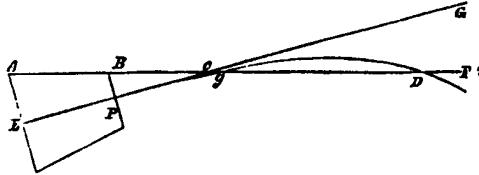
ABcF, the line passing through the highest points of the base ring and swell of the muzzle, or the muzzle band, or the top of the sight if there be one, is called the natural line of sight. EPeG is the axis of the piece or line of fire; the curved line PgD, described by the projectile, is called the trajectory, and is entirely below the line of fire, in consequence of the action of the force of gravity giving the projectile a downward tendency. The point D is called the point blank, and its distance from the mouth of the piece, the point-blank range.
7. Mention some of the causes which vary the point-blank range.
The form of the cannon; the weight or force of the charge; the diameter and weight of the projectile; and the inclination of the line of sight to the horizon.
8. Why has the form of the cannon an influence on the point-blank range?
Because as the difference between the diameter of the breech and muzzle becomes greater, the angle of sight, BcP= GcF (see fig.) increases, and the point blank D is removed further off; on the contrary, as the diameters approach to an equality, the
RANGES.
point blank approaches the piece. Within a certain angle, or when there is no angle of sight, as is the case with some old howitzers in which the line of sight is parallel to the axis of the bore, there will be no point blank, as the trajectory will be constantly below the line of sight.
9. What influence has the charge on the point-blank range?
An increase of the charge determines a more distant point blank; its diminution produces a contrary effect; but beyond a charge equal to one-third the weight of the ball, the increase of range is inconsiderable, and the force of the recoil becomes very great.
10. How do the diameter and weight of the projectile affect the range?
As the ball increases in size and density, it will overcome with more ease the resistance of the air.
11. Does the inclination of the line of sight to the horizon have much effect on the point-blank range?
Only when this inclination is very considerable. For the ordinary inclination, from 00 to 150, above or below the horizon, the difference may be wholly neglected.
12. What is the effect on the point-blank range of firing upwards under a large angle?
The action of the weight being nearly directly opposed to the impulsive force, the trajectory becomes compressed and the point-blank distance diminishes. The contrary effect obtains in firing downwards under a similar angle, as the weight and the force then act in nearly the same direction.
13. Why may the point-blank be considered constant for the same calibre?
HAND-BOOK OF ARTILLERY.
The dimensions, charges, and weights of projectiles, being constant, and the inclination of the natural line of sight, except in a very few cases, being comprised between 00 and 150, it follows that for the same calibre, the point blank may be considered constant, and may serve as a point of reference in firing at different distances.
14. What is the extreme range of a piece of artillery?
The distance from the piece to where the projectile finally rests.
15. For a given velocity what effect has an increase of the angle of fire on the range?
It increases with the angle of fare up to a certain limit, beyond which it diminishes.
10. What angle gives the greatest range in VACUO?
Forty-five degrees.
17. When will this angle give the maximum range in practice?
Only for feeble charges, and very heavy projectiles.
18. How is the angle of greatest range in practice affected by a change in the velocity and size of the projectile?
It seems to diminish as the velocity is increased, and as the ball is reduced. For the musket the angle of maximum range varies from 280 to 300 and is nearly 420 for mortars.
19. Under what angle is a mortar usually fired?
Under the constant angle of 450, and the charge is varied according to the range required.
NOTE.—When mortars are employed in firing on inclined planes, up or down bill, should the inclination be considerable, the
RANGES.
angle or greatest range, instead of being 450, is 450+½ the angle which the plane makes with the horizon.
Thus to strike an object elevated 180 above the plane on which the mortar rests, the angle or greatest range would be 450+7½0 = 52½0; if the object was depressed 150, the angle would be 450-7½0=37½0.
20.What are the advantages of this practice?
Economy of ammunition; the recoil being inconsiderable, the mortar and its bed receive but little strain; the ranges are more uniform, and the effect of a slight error in the angle of fire is less than with any other.
21. Is the mortar ever fired at any other angle than 450?
Yes; sometimes at 600.
NOTE—In this casethe range is about one-tenth less than that due to an angle of 450.
22.When is the mortar fired tinder an angle of 600?
When the battery is situated very near the object assailed, and it is desired that the shells may fall upon the magazines of the besieged. It is evident that projectiles the higher they are thrown up acquire more velocity in falling, besides striking the object more directly and with increased violence.
23. Under what angle were stone-mortars usually fired?
Under an angle of 600, and sometimes of 750; that, in falling from a great height, the stones might have the maximum force of’ percussion.
24. Under what angle should grenades be thrown from mortars?
About 330; otherwise they will be buried in
HAND-BOOK OF ARTILLERY.
the earth, and their fragments will not be sufficiently destructive.
25. When a gun or howitzer is aimed with the line of metal horizontal, what is the elevation equal to?
The natural angle of sight or dispart.
26. How is the time of flight for siege mortars at an elevation of 450 determined?
It is nearly equal to the square root of the range in feet divided by four.
NOTE.—The quotient gives the approximate time in seconds.
RANGES.
RANGES OF FIELD GUNS AND HOWITZERS.
|
KIND OF PIECE. |
POW-DER |
BALL |
ELEVA-TION |
RANGE |
REMARKS. |
|
8 pounder Field Gun. |
lbs. 1.25
1.25 |
Shot.“ “ “ “ “ Sph. case. “ “ “ “ |
0 ‘ 0 1 2 3 4 5 1 1 45 2 2 45 3 3 15 4 |
yds. 318 647 867 1138 1256 1523 600 700 800 900 1000 1100 1200 |
P.B. Range.
Time 2 seconds. “ 2 ¾ “ “ 3 “ “ 3 ½ “ “ 3 ¾ “ “ 4 “ “ 4 ½ “ |
|
12 pounder Field Gun Model 1841 |
2.5
2.5 |
Shot. “ “ “ “ “ “ Sph. case. “ “ “ “ “ “ |
0 1 1 30 2 3 4 5 1 1 45 2 2 15 2 30 3 3 30 |
347 662 785 909 1269 1455 1663 600 700 800 900 1000 1100 1200 |
P.B. Range
Time 1 ¾ seconds. ‘ 2 ½ “ “ 2 ¾ “ “ 3 “ “ 3 ¼ “ “ 4 “ “ 4 ½ “ |
|
12 pounder Field Gun Model 1857 |
2.5
2.5
2 |
Shot. “ “ “ “ “ Sph. case. “ “ “ “ “ “ Shell. “ “ “ “ “ “ “ |
0 1 2 3 4 5 0 30 1 1 30 2 3 3 30 3 45 0 0 30 1 1 30 2 2 30 3 3 45 |
325 620 875 1200 1320 1680 300 575 633 730 960 1080 1135 300 425 616 700 787 925 1080 1300 |
Time 1 Second. “ 1 ¾ “ “ 2 ½ “ “ 3 “ “ 4 “ “ 4 ¾ “ “ 5 “ Time 0 ¾ Seconds. “ 1 ¼ “ “ 1 ¾ “ “ 2 ¼ “ “ 2 ¾ “ “ 3 ½ “ “ 4 “ “ 5 “ |
![]()
HAND-BOOK OF ARTILLERY.
RANGES OF FIELD GUNS AND HOWITZERS. —Continued
|
KIND OF PIECE. |
POW-DER |
BALL |
ELEVA-TION |
RANGE |
REMARKS. |
|
12 pounder Field Howitzer. |
lbs, 1
2.5 |
Shell.“ “ “ “ “ Sph. case. “ “ |
0 ‘ 0 1 2 3 4 5 2 15 3 15 3 45 |
yds. 195 539 640 847 975 1072 485 715 1050 |
Time 2 seconds. “ 3 “ “ 4 “ |
|
24 pounder Field Howitzer. |
2
2,5 |
Shell.“ “ “ “ “ Sph. case. “ “ “ “ “ |
0 1 2 3 4 5 1 30 2 2 30 2 45 3 15 3 50 |
295 516 793 976 1272 1322 600 700 800 900 1000 1200 |
Time 2 seconds. “ 2 ½ “ “ 3 ¼ ” “ 3 ½ “ “ 4 “ “ 4 ¾ “ |
|
36 pounder Field Howitzer. |
2,5
3.25 |
Shell.“ “ “ “ “ Sph. case. “ “ “ “ “ “ |
0 1 2 3 4 5 1 30 2 2 15 2 45 3 3 35 3 45 |
290 531 779 1029 1203 1504 600 700 800 900 1000 1100 1200 |
Time 2 seconds. “ 2 ½ “ “ 3 “ “ 3 ½ “ “ 3 ¾ “ “ 4 ½ “ “ 4 ¾ “ |
|
Mountain Howitzer. |
0.5
0.5 |
Shell.“ “ “ “ “ “ “ “ “ “ “ |
0 1 2 2 30 3 4 5 0 2 30 3 4 4 30 |
170 300 392 500 637 785 1005 150 450 500 700 800 |
Time 2 seconds.
Time 3 seconds.
Time 2 seconds.
Time 2 ¾ sec’ds. Time 3 seconds. |
RANGES.
RANGES 0F HEAVY ARTILLERY.
|
KIND OF PIECE. |
POW-DER |
BALL |
ELEVA-TION |
RANGE |
REMARKS. |
|
|
18-Pdr. Siege and Garrison Gun on Barbette Carriage |
lbs. 4.5 |
Shot. “ “ “ “ “ |
0 ‘ 1 1 30 2 3 4 5 |
yds. 641 800 950 1256 1450 1592 |
Point Blank
|
|
|
24-Pdr. Siege and Garrison Gun on Siege Carriage. |
6 |
Shot. “ “ “ “ “ “ |
0 1 1 30 2 3 4 5 |
412 842 953 1147 1417 1666 1901 |
Point Blank
|
|
|
32-Pdr. Sea-Coast Gun on Barbette Carriage. |
6 8 |
Shot. “ “ “ “ “ “ “ |
1 45 1 1 30 1 35 2 3 4 5 |
900 713 800 900 1100 1433 1684 1922 |
|
|
|
42-Pdr. Sea-Coast Gun on Barbette Carriage. |
10.5 |
Shot. “ “ “ “ “ |
1 1 30 2 3 4 5 |
775 860 1010 1300 1600 1955 |
|
|
|
8-Pdr. Siege Howitzer on Siege Carriage. |
4
|
45 lb. shell. “ “ “ “ “ “ |
0 1 2 3 4 5 12 30 |
251 435 618 720 992 1241 2280 |
Time ¾ Seconds. “ 1 ½ “ “ 2 “ “ 3 “ “ 4 “ “ 5 “ |
|
|
4 24-Pdr. Siege Howitzer on a flank Casemate Carriage. |
2
1 ¾
2 |
17 lb. Shell. “ “ Sph. case. “ “ |
0 1 5 2 5 30 3 30 |
295 516 1322 600 1050 880 |
Time 2 seconds. “ 4 “ “ 3 “ |
|
HAND-BOOK OF ARTILLERY.
RANGES 0F HEAVY ARTILLERY. Continued.
|
KIND OF PIECE. |
POW-DER |
BALL |
ELEVA-TION |
RANGE |
REMARKS. |
|
8-in. Sea-Coast Howitzer on a Barbette Carriage. |
lbs. 4
6
8 |
45 lb. Shell. “ “ |
0 ‘ 1 2 3 4 5 1 2 3 4 5 1 2 3 4 5 |
yds. 405 652 875 1110 1300 572 828 947 1168 1463 646 909 1190 1532 1800 |
|
|
10-in. Sea-Coast Howitzer on a Barbette Carriage. |
12 |
90 lb. Shell. “ |
1 2 3 3 30 4 5 |
580 891 1185 1300 1426 1650 |
Time 3 seconds. “ 4 “
“ 5 ½ “ “ 6 “ |
|
10-in. Columbiad.
Axis of gun 6 feet above the horizontal plane. |
10 |
50 lb. Shell. “ Shot “ |
1 2 3 4 5 6 7 8 9 10 11 12 13 14 15 20 25 30 5 15 |
681 1108 1400 1649 1733 1944 2061 2250 2454 2664 2718 2908 3060 3123 3138 3330 3474 3873 1697 3224 |
Time 1.88 sec’ds. “ 3.58 “ “ 4.30 “ “ 5.41 “ “ 6.25 “ “ 7.56 “ “ 7.96 “ “ 9.12 “ “ 10.16 “ “ 10.91 “ “ 11.3 “ “ 13. “ “ 14.08 “ “ 14.25 “ “ 16. “ “ 18.40 “ “ 20. “ “ 25. “ “ 6.20 “ “ 14.19 “ |
RANGES.
RANGES 0F HEAVY ARTILLERY. Continued.
|
KIND OF PIECE. |
POW-DER |
BALL |
ELEVA-TION |
RANGE |
REMARKS. |
|
10-in. Columbiad.
Axis of gun six feet above the horizontal plane |
lbs. 15
18
20 12
18 |
Shell 100 lbs, “ “ “ “ Shot 125 lbs. “ Shell 100 lbs. “ “ “ |
0 ‘ 3 5 8 10 12 20 30 15 30 0 1 2 3 4 5 6 8 10 15 20 25 30 35 39.15 1 2 3 4 5 0 1 2 3 4 5 6 8 10 15 20 25 30 35 |
yds. 1008 1525 2238 2720 2847 3842 4836 3218 5163 394 753 1002 1230 1570 1814 2037 2519 1777 3525 4020 4304 4761 5433 5654800 1012 1184 1443 1604 448 747 1100 1239 1611 1865 2209 2489 2848 3200 3885 4150 4651 4828 |
Time 3.20 sec’ds. “ 5.64 “ “ 8.10 “ “ 10.98 “ “ 11.73 “ “ 18.92 “ “ 27.50 “ “ 14.32 “ “ 27.08 “
Axis of gun 15 feet above the water.
Shot ceased to richochet on water.
Time 1.9 sec’ds. “ 3.2 “ “ 3.6 “ “ 5.2 “ “ 6.5 “ “ 8.5 “ “ 10.0 “ “ 12.9 “ “ 16.0 “ “ 23.5 “ “ 26.9 “ “ 34.0 “ “ 36.9 “ |
HAND-BOOK OF ARTILLERY.
RANGES 0F HEAVY ARTILLERY. Continued.
|
KIND OF PIECE. |
POW-DER |
BALL |
ELEVA-TION |
RANGE |
REMARKS. |
|
15-in. Columbiad. |
lbs. 40
45 50 |
Shell 302 lbs. “ “ |
0 ‘ 0 1 2 3 4 5 6 7 8 9 10 12 15 20 25 28 30 25 “ |
yds. 273 484 812 1136 1310 1518 1760 1948 2194 2238 2425 2831 3078 3838 4528 4821 5018 4595 4680 |
|
|
10-in. Sea-Coast Mortar |
10 |
98 lb. Shell. |
45 |
4250 |
Time 36 sec’ds. |
|
10-in. Siege Mortar. |
1 1.5 2 2.5 3 3.5 4 |
90 lb. Shell. “ |
45 “ “ “ “ “ “ |
300 700 1000 1300 1600 1800 2100 |
Time 6.5 sec’ds. “ 12 “ “ 14 “ “ 16 “ “ 18 “ “ 19 “ “ 21 |
|
8-in. Siege Mortar. |
lb. oz. 0 10 0 13 1 1 2 1 3 1 4 1 5 |
46 lb. Shell. “ |
45 “ “ “ “ “ “ |
500 600 750 900 1000 1100 1200 |
Time 10 sec’ds. “ 11 “ “ 12 ½ “ “ 13 “ “ 13 ½ “ “ 14 “ “ 14 ½ “ |
|
24-Pounder Coehorn Mortar |
oz. 0.5 1 1.5 1.75 2 2.75 4 6 8 |
17 lb. Shell. “ |
45 “ “ “ “ “ “ “ “ |
25 68 104 143 165 260 422 900 1200 |
|
RANGES
RANGES WITH SEA-COAST 13-INCH MORTARS, 200 ELEVATION.
|
Charge. |
Mean time of flight. |
Least range. |
Greatest range. |
Mean range. |
|
lbs. 4 6 8 10 12 14 |
Seconds 8 9.5 11.66 12.50 14.25 15.25 |
yards. 840 1209 1653 2010 2369 2864 |
yards. 877 1317 1840 2128 2688 2780 |
yards. 869 1263 1744 2066 2528 2722 |
RANGES WITH 13-INCH MORTARS, AT 450 ELEVATION.
|
13 –inch mortar. |
Powder. |
Shell. |
Elevation. |
Range |
|
|
lbs. 20 |
lbs. 200 |
450 |
yards. 4325 |
RANGES WITH 13-INCH MORTARS, AT 450 ELEVATION.
|
Charge. |
Flight. |
Fuze. |
Range. |
|
Lbs. Oz. 7 7 8 8 8 8 9 9 8 10 10 8 11 11 8 12 12 8 13 13 8 14 14 8 15 15 8 16 16 8 17 17 8 18 18 8 19 19 8 20 |
Seconds. 21.4 22.4 23.2 23.8 24.4 24.9 25.4 25.9 26.8 26.7 27.0 27.4 27.7 28.0 28.3 28.5 29.0 29.1 29.2 29.4 29.6 29.8 29.8 30.0 30.2 30.3 30.5 |
Inches. 10ths. 4 2 ¾ 4 4 4 6 4 7 ½ 4 8 ¾ 4 9 ¾ 5 1 5 1 ¾ 5 2 ½ 5 3 ½ 5 4 5 4 ¾ 5 5 ½ 5 6 5 6 ½ 5 7 5 8 5 8 ¼ 5 8 ½ 5 8 ¾ 5 9 5 9 ½ 5 9 ¾ 6 0 6 0 ¼ 6 0 ½ 6 1 |
yards. 2190 2346 2480 2600 2734 2853 2958 3026 3150 3246 3327 3404 3470 3552 3617 3681 3739 3797 3849 3901 3949 3997 4040 4085 4123 4160 4200 |
HAND-BOOK OF ARTILLERY.
RICOCHET.
1. What is understood by RICOCHET FIRING?
That obtained by firing a piece at very small angles of elevation, by which means the projectile which falls on ground of ordinary firmness at an angle not greater than 100, or upon water at 40 or 50, will make one or more bounds. In this case the projectile is said to ricochet.
2. What is the object of ricochet firing?
To enfilade a face of the enemy’s work, which is effected by causing a projectile to bound along the terreplein of the face with the view of annoying his cannoneers, and dismounting his pieces. It is employed also in harassing an enemy, when formed or in the act of forming behind a rising ground or other obstacle, taking post in a wood, &c.; and in enfilading a line of troops.
8. What are the peculiar advantages of this fire?
In being able to reach objects which cannot be reached by direct fire, on account of intervening obstacles.
4. In enfilading a face of an enemy’s work, what is the object to be fired at?
Usually some point of the interior crest of the
RICOCHET.
parapet which covers a flank of the terreplein to be reached.
5. What is the POINT OF FALL?
The point of the terreplein which is first struck by the projectile, after having grazed the interior crest.
6. What is the ANGLE OF FALL?
It is the angle made at the poiint of fall by the tangent to the trajectory with a horizontal line in the plane of fire.
7. How does the angle of fall compare with that of ELEVATION?
It is greater.
8. Upon what do the charge and elevation depend?
Upon the distance of the object from the battery; upon the difference of level between these points; the distance of the desired point of fall from the parapet; the height of the parapet, &c.
9. If the embrasure be such that the object is masked, how is the piece pointed?
The direction must be given, as with the mortar, by the plummet; this is held by the person who points, in such a manner as to cover both the line of metal and the object. The elevation is then given by the quadrant.
10. What is the maximum angle of elevation in ricochet firing?
Against troops it should seldom exceed 30 above the surface of the ground occupied by them. Against fortresses, forts, and fortified lines, it varies from 30 to 90 above the horizontal.
11. At what distance from the object should the ricochet battery be placed?
HAND-BOOK OF ARTILLERY.
Never at a greater distance than 600 yards.
12. In enfilading a work, How should the ricochet firing be conducted?
The projectile should be made to graze the parapet, while in the descending branch of the trajectory; and this must be effected by regulating the charges and elevating or depressing the piece until the shot is seen to fall just over the interior crest of the parapet. Light charges are generally used, varying from two-thirds to one-eighth of the ordinary charge.
13. What pieces are best adapted for ricochet fire?
Those which throw heavy shells; for, if used to enfilade a work, the shells lodge and explode in the traverses, and render the guns more liable to be dismounted and their detachments put hors de combat.
14. What determines the NATURE of the ricochet?
The angle of fall: it is flattened when this angle does not exceed 40, and curvated when it is between 60 and 100. In the first of these fires, the velocities are great, and in the second small.
15. What are the charges for a FLATTENED RICOCHET for siege gun. at an angle of about 30?
See Table, page 83.
16. What are the charges for a FLATTENED RICOCHET for siege howitzers at an angle of about 30?
See Table, page 83.
17. What are the charges for a CURVATED RICOCHET for a Siege howitzer at an angle of about 100?
See Table, page 83.
RICOCHET.
CHARGES FOR A FLATTENED RICOCHET FOR A
SIEGE GUN.
DISTANCE |
ELEVATION |
CHARGE |
|
660 yards. 550 “ 440 “ 330 “ |
20 45’ 30 30 15’ 30 35’ |
1/12 weight of ball. 1/18 “ “ 1/25 “ “ 1/35 “ “ |
CHARGES FOR A FLATTENED RICOCHET FOR A
SIEGE HOWITZER.
DISTANCE |
ELEVATION |
CHARGE |
|
660 yards. 550 “ 440 “ 330 “ |
10 45’ 20 15’ 20 15’ 20 45’ |
2 lbs. 2 lbs. 8 oz. 1 lb. 12 oz. 1 lb. 2 oz. |
CHARGES FOR A CURVATED RICOCHET FOR A
SIEGE HOWITZER.
|
DISTANCE |
ELEVATION |
CHARGE |
REMARKS |
|
660 yds. 440 “ 330 “ 220 “ |
70 30’ “ “ “ |
1 lb. 4 oz. 1 lb. 1 oz. 14 oz. 10 oz. |
The weight of the object above the level of the battery being supposed to be twenty feet. |
HAND-BOOK OF ARTILLERY.
REC0IL.
1. What is meant by the RECOIL of a piece of artillery?
The retrograde motion impressed upon cannon by the discharge is termed the recoil.
2. What causes the recoil of a piece?
The gas produced by the ignition of the charge in the, bore, expanding with equal force in every direction finds only two ways of escape (the muzzle and vent); the pressure upon these points will therefore cease, while it will be proportionally increased upon the parts directly opposite, that is, the breech and the lower part of the first reinforce, producing in the first case the recoil, and in the other, indirectly, the dipping of the muzzle.
3. How far does a gun usually recoil?
This depends entirely upon the nature and inclination of the ground upon which the carriagestands, the situation of the trunnions, angle of elevation, comparative weight of the gun and carriage, and upon the strength of the charge.
4. What proportion does the velocity of the recoil of a piece bear to that of a ball?
Inversely as their weights, or masses.
5. What proportion exists between the pressure
acting
upon the part of the bore of a piece directly
RECOIL.
opposite the went, and that which occasions the recoil?
As the square of the diameter of the vent is to the square of’ that of’ the shot.
6. Has the recoil any effect upon the flight of the projectile?
No appreciable effect, the shot being expelled from the gun before it has recoiled a fraction of an inch.
7. What arc the principal inconveniences arising from the recoil of guns?
The necessity of running up the gun after every discharge, and consequent fatigue to tine men and loss of time; it also necessitates that a greater breadth should be given to the terreplein of a work.
8. What causes the muzzle of a piece of artillery to dip when fired?
The sudden pressure of the gas acting upon the portion of the first reinforce opposite to the vent, causes the piece to strike downwards upon the elevating screw or quoin, and the reaction to make the muzzle dip.
9. What influence has the position of the axis of the trunnions in respect to that of the bore upon the recoil?
If the axis of the trunnions be below that of the piece, the pressure of’ the breech uponthe carriage will increase. ns the distance between the axles increases; and from this pressure there will arise a friction upon the ground which will diminish the recoil. On the contrary, if the axis of the trunnions be above that of the piece, the breech will have an upward tendency, the recoil will he in-
HAND-BOOK OF ARTILLERY.
creased, but the carriage, and particularly the axle tree, will be subjected to less strain. Hence, the recoil will be transmitted directly to the trunnions, if their axis (as in our service) be situated in the same plane with the axis of the piece. The size of the trunnions is made proportional to the force of the recoil.
10. Does the position of the trunnions with reference to the centre of gravity of the piece influence the recoil?
Yes; in cannon fired horizontally, or under very small angles, the portion in rear of the truninions is heavier than that in front; an arrangement which increases the pressure of the trail on the ground so as to diminish the recoil. But in pieces fired under large angles, the trunnions are placed In rear of the centre of gravity, for the purpose of increasing the ease of pointing.
WINDAGE.
W I N D A G E.
1. What is meant by WINDAGE?
The difference between the diameter of the projectile and that of the bore.
2. Is it absolutely necessary to allow windage?
Yes, in order to make an allowance for a piece becoming foul, the expansion of shot by heat, the incrustation of rust, and for the tin straps of fixed ammunition.
3. What advantages are derived from reducing the windage?
An increase in the accuracy of fire; a more extensive range, or an equal range with a smaller charge, as there is less loss of gas; and less injury to the surface of the bore.
4. Why should the bore suffer less injury by a diminution of the windaqe?
Because in proportion to the decrease of windage there will be less space for the reflections of the shot along the bore, and consequently less injurious power exercised upon it.
5. What is the loss of velocity by a given windage proportional to?
It is directly as the windage, and inversely as the diameter of the bore very nearly.
HAND-BOOK OF ARTILLERY.
6. What is the loss of velocity by the windage of the ball?
|
KIND OF GUN. |
Charge of powder. |
Initial velocity of ball. |
Loss of velocitybyWindageof1-40th diam. |
||
|
Without windage. |
With windageof 1-40th diam. |
||||
|
32-pdr. Sea-Coast |
lbs. 4 |
feet. 1444 |
feet. 1271 |
feet. 178 |
Per cent 12 |
|
24-pdr. Siege |
4 6 |
1600 1890 |
1458 1728 |
167 167 |
10 9 |
|
12-pdr. 25 calibres |
2 3 4 |
1617 1915 2124 |
1444 1742 1951 |
173 173 173 |
11 9 8 |
|
12-pdr, Field, 18 cal-ibres |
2 3 4 |
1529 1793 1992 |
1370 1635 1834 |
158 158 158 |
10 9 8 |
|
6-pdr. Field |
1.5 |
1734 |
1560 |
174 |
10 |
7. What windage is allowed to guns?
IRON |
BRASS
|
|||||||
Sea-Coast |
Siege and Garrison |
Field |
Field |
|||||
|
42 |
32 |
24 |
18 |
12 |
Rifled 4 ½ in. |
Rifled 3 in. |
12 |
6 |
|
in. 0.16 |
in. 0.15 |
in. 0.14 |
in. 0.13 |
in. 0.10 |
in. 0.05 |
in. 0.05 |
in. 0.10 |
in. 0.09 |
WINDAGE.
8. What windage is allowed to columbiads and howitzers?
COLUMBIADS*
|
HOWITZERS |
||||||||
|
IRON |
IRON
|
BRASS |
|||||||
|
Sea-Coast |
*Siege and Garrison |
Field |
Mntn |
||||||
|
10 in. |
8 in. |
10 in. |
8 in. |
8 in. |
24 pdr. |
32 pdr. |
24 pdr. |
12 pdr. |
12 pdr. |
|
in. 0.12 |
in. 0.12 |
in. 0.12 |
in. 0.13 |
in. 0.13 |
in. 0.14 |
in. 0.15 |
in. 0.14 |
in. 0.10 |
in. 0.10 |
9. What amount of windage is allowed to mortars?
|
IRON
|
BRASS |
|||
|
Heavy
|
Light |
Coehorn 24-pdr. |
||
|
inches. 0.13 |
inches. 0.13 |
inches. 0.13 |
inches. 0.12 |
inches. 0.14 |
|
|
|
|
|
|
*Each of the new model Columbiads Is allowed a windage of 0.13 Inch; and the now model 8.in. Siege Howitzer a windage of 0.12 inch.
HAND-BOOK OF ARTILLERY.
GUNPOWDER.
1. What are the ingredients in GUNPOWDER?
Saltpetre, charcoal, and sulphur.
2. What are the proportions?
In the United States, 75 to 76 saltpetre, 14 to 15 charcoal, and 10 sulpher.
England, 75 Saltpetre, 15 Charcoal 10 Sulphur.
France, 75 “ 12 ½ “ 12 ½ “
Prussia, 75 “ 13 ½ “ 11 ½ “
3. What is the combustible ingredient?
Charcoal.
4. What is the use of saltpetre?
It furnishes the oxygen necessary to support a rapid combustion, and to change the whole mass into gas.
5. What is the use of sulphur?
It adds consistency to the mixture and intensity to the flame, besides rendering the powder less liable to absorb moisture.
6. On what dies the quality of gunpowder depend?
On the intimate mixture and proper proportions and purity of the ingredients.
7. In what does the manufacture of gunpowder consist?
In pulverizing the ingredients, incorporation,
GUNPOWDER.
compression, granulation, drying, glazing, and dusting.
8. Explain the method of making gunpowder by the pounding mill?
The charcoal in small pieces is first placed in the mortars, with a quantity of water, and pounded for half an hour; after which the saltpetre and then the sulphur, previously pulverized and sifted, are put in, and the whole well mixed with the hand; it is then pounded in the mortars and at the end of each hour, the composition is passed from each mortar into the next. At the sixth or eighth change, it is then pounded two hours without changing the mortars, in order that it may form into cake. It is then partially dried, and grained into a graining sieve, or passed between wooded rollers. The grains are then sifted to separate those which are too course and too fine, and also to separate from each other the different grains for cannon, musket, and rifle powder, It is then glazed in large glazing barrels, which make 15 or 20 revolutions in a minute. A charge of 500 lbs. Is thus treated for about 24 hours. It is then dried either in the open air or in a drying house. If in the open air, when the sun is too hot, the powder should be covered to prevent the loss of sulphur. It is then dusted, by being sifted in fine sieves, or through bolting cloths.
9. What other machines besides the pounding mill are used in pulverizing and incorporating the ingredients of gunpowder?
Rolling barrels, and the cylinder or rolling mill.
HAND-BOOK OF ARTILLERY.
10. What advantage is gained by the use of the ROLLING BARRELS?
It lessens the duration and danger of pounding in the mortars. After the ingredients are pulverized and mixed in the rolling barrels, the mixture is placed under the pestles of the pounding mill, 10 per cent, of water is added, and it is beaten for three hours only.
11. Which mill is now generally used?
The CYLINDER MILL, which performs at the same time the operations of pulverizing, incorporating, and pressing the composition. It consists of two cylinders, of marble or cast iron, weighing about fits tons each, rolling in a circular trough of the same material, the inner diameter of which is about three feet; a wooden plough follows the cylinders, to bring the powder towards the centre of the trough. The cylinders revolve ten times in a minute, and run from one to three hours on each charge of 50 lbs. of composition.
12. Does powder inflame instantaneously?
No; its inflammation is gradual and progressive, and in a gun the projectile commences to move before the whole charge is ignited.
13. Why should gunpowder be grained?
In order to facilitate the transmission of the flame. When the powder is very fine, and in large and compact charges, the flame cannot penetrate it, and it burns slowly and in successive layers.
14. Which burns quickest, the small or large grained powder?
Before coming to the limit of dust, the smaller the grain, the more rapid the combustion, and the greater the bursting force of the powder.
GUNPOWDER.
15. What is the difference between the ignition and combustion of large and small grained powder?
With the large grained, the ignition is more rapid, but the combustion slower; with small grains, the contrary is the case.
16. Why should the grains be angular?
Because they present a greater surface to the action of the flame, and therefore burn quicker.
17. Why should powder be free from dust?
Because the dust fills up the intervals between the grains, and forming a compact mass, retards combustion.
18. To what special purpose arc large and small grained powders applied?
The large for cannon, and the small for small arms.
19. How is the size of the grain for each kind of powder tested?
By means of sieves or gauges.
20. How many grains of powder are in 10 gra. Troy weight?
Cannon, 150; Musket, 2,000 to 2,500; and Rifle, 12,000 to 15,000.
21. What is the object in glazing powder?
Glazed powder does not absorb moisture, or break up in transportation, so much as unglazed.
22. What is the established mode of proving the strength of powder in the U. S.?
At least 50barrels of powder are thoroughly mixed together. One barrel of this is proved by firing three rounds from a musket with service charge, if it be musket powder; if cannon powder, from an 8.inch columbiad, with 10 lbs., and a solid shot of 65 lbs. weight, and 7.88 inches diameter; if
HANDBOOK OF ARTILLERY.
it be mortar powder, from an 8-inch mortar, with 1.25 lbs. and a shell 7.88 inches in diameter, weighing 47.5 lbs. The general character of the grain and its freedom from dust are noted.
23. How is the initial velocity determined?
By the Ballistic Pendulum, or by the ElectroBallistic Machine of Navez, or of Capt. Benton. (See Ord. Manual, p. 249.)
24. How is the strain upon the gun determined?
By the pressure piston of Capt. Rodman. (See Ord. Manual, p. 251.)
25. What is understood by the GRAVIMETRIC DENSITY of powder?
It is the weight of a given measured quantity. It is usually expressed by the weight of a cubic foot in ounces.
28. What should be the SPECIFIC GRAVITY of gunpowder?
Not less than 1.75.
27. What is the hygrometric proof of powder?
Samples are placed in shallow tin pans, set in a tub, the bottom of which is covered with water; the pans should be about an inch above the water, and the tub covered. Good powder will not absorb more than 2 ½ per cent, of moisture in 24 hours.
28.bbHow can the relative quickness of two kinds of powder be determined?
By burning a train laid in a circular or other groove, which returns into itself, made in a piece of hard wood: one-half of the groove being filled with each kind of powder, and fire communicated at the junction of the two trains, the relative quickness is readily deduced from observation of the point at which the flames meet.
GUNPOWDER.
29. What are the qualities of good powder?
It should be perfectly free from dust, uniform in strength and size of grains, angular and irregular in form; in color, brownish black, or slate color; so bard as not to be easily crushed by pressure with the finger; and should leave no beads or foulness when flashed in quantities of 10 grs. on a copper plate. It should give the required initial velocity to the ball, and not more than the maximum pressure on the gun, and should absorb but little moisture from the air.
30. What is the expansive velocity, and pressure of ignited powder ?
The expansive velocity is about 5,000feet per second, and pressure about 2,000 atmospheres.
31. What is the weight of a cubic inch of powder?
About half an ounce; a cubic foot will therefore weigh about 54pounds, and 32 cubic inches, one pound.
32. How is government powder packed?
In barrels of 100 lbs. each; the barrels being large enough to allow sufficient space for the powder to move when rolled to prevent its caking.
33. How are the barrels marked?
On both heads (in white oil-colors, the head painted black), with the number of the barrel, the name of the manufacturer, year of fabrication, and the kind of powder,—cannon, mortar, or musket,— the mean initial velocity, and the pressure per square inch on the pressure piston. Each time the powder is proved, the initial velocity is marked below the former proofs, and the date of the trial opposite it.
HAND-BOOK OF ARTILLERY.
34. When powder is injured by dampness, can it be restored!
If the water absorbed does not exceed 7 per cent., it can be by drying. If it has absorbed from 7 to 12 per cent., after drying it remains porous and friable, and is unfit for transportation. In this case it is better to work it over.
35. How is powder stored?
In magazines especially constructed for the purpose. The barrels are generally placed near the sides, three tiers high, or four tiers if necessary; small skids should be placed on the floor sad between the several tiers of barrels in order to steady them, and chocks should be placed at intervals on the lower skid, to prevent the rolling of the barrels.
36. How are the different kinds of powder arranged!
Those barrels of the same kind, place, and date of fabrication, &c., are piled together.
37. Should it be necessary to pile the barrels more than four tiers high, what is done?
The upper tiers are supported by a frame resting on the floor, or the barrels may be placed on their heads with boards between the tiers.
38. What is necessary for the preservation of the powder?
The magazine should he opened and aired in clear, dry weather, when the temperature of the air outside is lower than that inside. It should not be opened in damp weather if it can be avoided. The ventilators must be kept free; no shrubbery or trees should be allowed to grow so near as to protect the building from the sun.
GUNPOWDER.
39. How may the moisture of a magazine be absorbed?
By chloride of calcium suspended in a box under the arch, and renewed from time to time.
40. When the magazine is open, what precautions should be observed?
The sentinel or guard should have no fire-arms, and any one who enters it should take off his shoes, or put socks over them. No sword or cane, or any thing which might occasion sparks should be carried in.
41. How should powder in barrels be transported?
The barrels should never be rolled; they should be carried in hand-barrows or slings made of rope or leather. In wagons, the barrels should be packed in straw, and not allowed to ml, against each other, and the whole covered with thick canvas. In transportation by railroad, each barrel should be carefully boxed and packed so as to avoid all friction. The barrels should have a thick tarpaulin under them, and the cars should have springs similar to those of passenger ears.
42. What precaution should be used to prevent powder caking?
The barrels should be taken outside the magazine and rolled on boards.
43. Where should cartridge bags be filled?
In the filling room of the laboratory, or a small magazine, and not in the general magazine.
HAND-BOOK OF ARTILLERY.
PROJECTILES.
I. What projectiles are made use of in the service?
Solid shot; shells; spherical case, or shrapnel canister; grape; grenades; carcasses; light and fire balls.
2. What is a solid shot?
A solid sphere of cast iron, almost exclusively appropriated to guns. The gun usually derives its denomination from the weight of the shot, as 6-pr., 12-pr., &c.
3. What is a shell, and its use?
A hollow sphere of cast-iron, containing powder, which is ignited by means of a fuze; when fired at troops, it should be prepared to burst over their heads, or, if the ground be favorable, to ricochet a little in front, and plunge into the column. When fired at works or buildings, it should explode after penetration.
4. What is spherical-case, and what advantages does it possess?
It is a shell much thinner than the ordinary shell, and filled with leaden bullets and a charge of powder sufficient to burst it, which is done by means of a fuze as with a common shell at any required distance. It is thus calculated to extend all
PROJECTILES.
the advantages of canister shot, to distances far beyond the reach of that projectile. It is fired both from guns and howitzers.
5. What are canister shot?
Cylindrical tin cases with iron heads, of calibre suitable for different pieces of ordnance, filled with cast-iron balls arranged in four tiers, and packed in with dry saw-dust; they are fired at ranges not exceeding 400 yards, but their most destructive effects are from 100 to 200 yards.
6. What are grape shot?
A certain number of iron balls, usually nine, put together by means of two cast-iron plates, two rings, and one pin and nut. Each plate has on the inside three beds for the shot, of a depth equal to half the thickness of the plate, and of the form of a spherical segment, the curvature of which is the same as that of the shot. An iron pin riveted to the bottom iron plate, passes through the centre and also through the top plate, where the whole is secured by a nut and screw.
NOTE—The use of these shot for field pieces has been discontinued, canister answering the purpose of these shot.
7. How were the balls fixed in the old pattern?
They were placed in tiers around an iron pin attached to an iron tompion at the bottom, and put into a canvas bag, and then quilted around with a strong cord.
S. What is a grenade?
A shell thrown from the hand, or in barrels from mortars of large calibre, and ignited as other shells by means of a fuze.
9. How many kinds of grenades are made use of?
HAND-BOOK OF ARTILLERY.
Hand-grenades and rampart-grenades; six-pounder spherical case may be used for the former, and shells of any calibre for the latter.
10. To what purposes are grenades applied!
They are useful in the defence of works, the smaller, thrown by hand into the head of a sap, trenches, covered way, or upon the besiegers mounting a breach; the larger kinds are rolled over the parapet in a trough.
11. What is a carcass, and its use?
It is a spherical shell having three additional holes, of the same dimensions as the fuze hole, pierced at equal distances apart in the upper hemisphere of the shell, and filled with a composition which burns with intense power from eight to ten minutes, and the flame issuing from the holes sets fire to every thing combustible within its reach; it is used in bombardments, setting fire to shipping, &e.; and is projected from cannon like a common shell.
12. What is a substitute for a carcass?
Common shells loaded in the following manner: The bursting charge is placed in the bottom of the shell in a flannel bag, over which carcass composition is driven until the shell is nearly filled; then insert four or five strands of quick-match, which must be secured by driving more composition upon it. These shells, after burning as a carcass, explode.
13. What is a fire-ball, and its use?
It is a projectile of an oval shape, formed of sacks of canvas filled with combustible composition which emits a bright flame. Its use is to light
PROJECTILES.
up the enemy’s works, and it is loaded with a shell to prevent it from being approached.
14. What is a light ball?
Light balls are the same as fire balls, except that there is no shell in them, as they are used for lighting up our own works.
15. What is a smoke ball?
A hollow paper sphere similar to a light ball, and filled with a composition which emits a dense, nauseous smoke; it is employed to suffocate the enemy’s miners when at work, or to conceal one’s own operations; it burns from twenty-five to thirty minutes.
16. In field pieces to what is the projectile attached?
To a block of wood called a sabot.
17. Are the projectile and cartridge ever attached to the same sabot?
Yes, in field guns, and the 12-pdr. field and mountain howitzers; the whole then constitutes a round of fixed ammunition.
18. What is the arrangement in case of the 32 and 24-pdr. field howitzers?
The projectile is separate from the charge, and the cartridge is attached to a block of wood called the cartridge-block, the object of which is to give a finish to the cartridge and fill the chamber.
19. What difference is there in sabots for field service?
Sabots for shot, and spherical-case for guns, have one groove for attaching the cartridge—those for gun canisters and for the 12-pdr. howitzer shells, spherical-case, and canisters, have two grooves. Those for the 32 and 24-pdr. howit-
![]()
HAND-BOOK OF ARTILLERY.
zers have no grooves; but are furnished with handles made of cord, passing through two holes in the sabot, and fastened by knots on the inside.
20. How are projectiles for field service fastene4 to the sabot?
By straps of sheet-tin, or of strong canvas, when tin or sheet iron cannot be procured.
21. How many straps are employed, and how are they fastened?
For shot, there are two straps crossing at right angles, one passing through a slit in the middle of the other. For shells, there are four straps soldered to a ring of tin, or fastened to it by cutting four slits in the ring, into which the upper ends of the strap are hooked, and turned down on the inside of the ring. The sabots for 32 and 24-pdr. field howitzers having no groove, each strap is fastened by one nail on the side, and two under the bottom of the sabot.
22. What is a CANISTER FOR FIELD SERVICE?
It consists of a tin cylinder attached to a sabot and filled with cast-iron shot.
23. How is it made?
The cylinder is fastened to the sabot by six or eight nails, and a plate of rolled iron is placed at the bottom on the sabot. It is closed with a sheet-iron cover after being filled, the top of the cylinder being cut into strips ½ an inch long, and turned down over the cover.
24. In case of heavy guns are the shot attached to the sabot?
They are generally without a sabot.
25. How is it with shells and spherical case?
Except for the 8-inch siege howitzer, they are all
PROJECTILES.
strapped to sabots made of thick plank, with strips of tin, as in case of strapping shot for field service.
26. How is it with canister for siege and sea coast guns?
They have no sabot; the tin is turned over the iron bottom.
27. How is it with canisters for the 8-in, siege and sea-coast howitzers?
They are attached to sabots in the same way as the field-howitzer canisters. The sabot for the siege howitzer has a hemispherical bottom and the seacoast a conical one, to suit the connecting surface between the cylinder of the bore and the chamber in these Pieces.
28. Are sabots used with grape shot?
Yes, in the 8-inch sea-coast howitzer.
29. What is its form, and how fastened?
It is conical; and may be fastened to the lower plate with screws, or the pin may be made long enough to pass through it; or else the sabot may be inserted into the piece separately from the stand of grape.
30. What is the object of fixing shot or shells to wooden bottoms?
To prevent injury to brass cannon; and to insure the fuze of a shell being retained in or near the axis of the piece.
31. What proportion does the weight of one shot bear to that of another!
The proportion is, as the cubes of their diameters.
32. How is the weight of a cast-iron shot or shell determined!
Multiply the cube of the diameter of the shot
HAND-BOOK OF ARTILLERY.
in inches, or the difference of the cubes of the exterior and interior diameters of the shell by 0.134 for the weight in pounds. Incase of lead balls, the multiplier is 0.214.
The cube of the radius in inches of a cast-iron shot will be very nearly equal total weight in pounds.
33. How is the diameter of a cast-iron shot of a given weight found?
Divide the weight in pounds by 0.134, and extract the cube root of the quotient, which will be the diameter in inches.
34. How is the quantity of powder which a shell will contain found?
Multiply the cube of the interior diameter of the shell in inches, by 0.01744 for the weight of powder in pounds.
Note.—These multipliers are found as follows: Suppose W to represent the weight of a body, D its density, V its volume, and g the weight of the unit of mass, then W=DVg Now, if a cubic inch of distilled water at the standard temperature be taken as the unit of mass, g will be numerically 62.5/1728 pounds. Hence, W=DV 62.5/1728=0.O36201DV
x
=O.O362OlD –d3 (supposing d to be the diameter and the
6
body to be spherical)=O.036201 x 0.5238Dd3=O.O18955Dd3. If we now substitute for D the specific gravity of cast-iron shot or shells=7.OOO, we have W=7 x 0.O18955d3=O.134d’; and if for D we substitute the specific gravity of lead, W= 0.2142d3 ;and in case of powder W=O.01744d3.
For diameters, weights, and charges, see Tables, pages
114—117.
35. When shot are heated to a white heat, what expansion takes place?
PROJECTILES.
Calibre
|
8-in. |
42 |
32 |
24 |
18 |
12 |
|
Expansion…….inches
|
0.149 |
0.11 |
0.10 |
0.08 |
0.06 |
0.04 |
36. Do heated shot retain a permanent enlargement?
Yes; in case of the 8-in, shot, for example, after the first cooling the enlargement is 0.054 in.; and, after the second, 0.099 in.
37. Are the igniting powers of a hot shot destroyed by ricochetting upon the water?
No; a shot, properly heated, will ignite wood after having struck the water several times.
38. What is the peculiarity of cartridges for hot shot?
There are two cartridge bags, one being inserted, choke foremost in another of the next higher calibre, and the end of the latter folded under.
39. Explain the process of loading with hot shot.
The piece should be sponged with great care, and the worm frequently passed into the bore. As a precaution, it is well to insert a wet sponge just before putting in the ball. The muzzle is sufficiently elevated to allow the ball to roll down the bore, the cartridge is inserted, the mouth of the outer bag foremost, the fold down, and carefully pushed home without breaking it; a dry hay-wad is placed upon it, and rammed once;then a clay or wet hay-wad, and rammed twice; and finally, if firing at angles of depression, a wad of clay a half-calibre in length, or a wet hay-wad is puton the ball.
HAND-BOOK OF ARTILLERY.
40. May the ball cool in the gun without igniting the charge?
Yes, with proper precaution in loading. The piece, however, should be fired with as little delay as possible, as the vapor, which arises from the action of the hot ball on the water contained in the wad, diminishes the strength of the powder.
41. What means are afforded at the sea-board forts for heating shot?
Furnaces for this purpose are erected, which hold 60 or more shot.
42. What length of time is required to heat them to a red heat!
The shot being placed and the furnace cold, iti requires one hour and fifteen minutes; but after the furnace is once heated, a 24-pdr. shot is brought to a red heat in twenty-five minutes; the 32-pdr. and 42.pdr. shot require a few minutes longer.
43. Describe grates for heating shot.
In siege and other batteries, where there are no furnaces, a grate is used. It consists of four bars 1.75 inches square, three feet long, placed four inches apart on three iron stands, with legs one foot in height. It is placed in an excavation one foot in depth, of the width of the grate, perpendicular at the back and side, open in front, the legs resting on bricks or stones rising about four or five inches from the bottom. A reef is made over it with hoops of flat iron, covered with sods and eighteen inches of earth, having in the back part a chimney six inches square. The shot are placed on the back part of the grate, leaving one-fourth of the front part free; and under and on the front part the wood is put, cut in pieces about fourteen inches
PROJECTILES.
long and two inches thick. A thick sod is used as a register, to regulate the draught of the chimney, so that no flame can issue from the front. This grate, which will contain about fifteen 24.pdr. balls, heats them to a red heat in an hour, and will supply three guns.
46. How are wads for firing hot shot made?
Of hay; by twisting from the hay a rope of an inch or an inch and a half in diameter, and then commencing at one end, and doubling it up about one caliber in length, twisting it all the time until it becomes nearly large enough, when the rope is wound around the wad perpendicular to its axis, and fastened with a hitch. Or the hay may be rammed in a form of proper caliber, and then bound with spun yarn, and afterwards rammed a second time.
46. Have hot shot been almost entirely superseded?
Yes; since the adoption of the method of throwing large hollow shot from long pieces. These require but little preparation, can be used at once, and are more terrible in their effects.
46. What are ring or GROMMET wads, and their use?
They consist of a ring of rope yarn* about 0.7 in. thick, with two pieces of strong twine tied across at right angles to each other. The size of the ring is the full diameter of the bore, in order that it may fit tight, and stop the windage. They increase the accuracy of fire, and are to be preferred when the object of the wad is to retain the ball in its place, as in firing at a depression. They stop the windage best when placed behind the ball.
*They may also be made of straw formed Into rings of the proper size, and wrapped with twine, and tied to the ball.
HAND-BOOK OF ARTILLERY.
They may be attached to the straps, or to the ball by twine, or may be inserted like other wads after the ball.
47. How are JUNK-WADS made; and for what are they used?
Wad-moulds for each calibre,—consisting of two cast-iron cylinders of different diameters set in oak, or of two strong pieces of oak, strapped with iron, and joined by a hinge,—are employed in their manufacture. The junk, after having been picked, is compressed by being beaten in the smaller mould with a maul and cylindrical drift—the latter nearly of the size of the mould—until it assumes the requisite dimensions; it is then taken out by raising the upper part of the mould, and closely wrapped with rope yarn, passed over it in the direction of the axis of the cylinder, and fastened by a few turns around the middle of the wad. It is then placed in the large mould, and again beaten with the maul and drift until its diameter is increased to that of the mould, when it is taken out and its diameter verified by a wooden gauge corresponding to the large shot-gauge of the calibre. These wads are used for proving cannon.
48. Describe the process of loading field-shells.
They are set up on their sabots, the charges measured out in the proper powder-measure, and poured in through a copper funnel. The fuze~plugs are then driven in with a mallet, allowing the tops to project about 0.1 in., care being taken not to split them. The holes in the plugs are then carefully reamed out, and stopped- with tow-wads which are pressed in firmly with a round stick.
PROJECTILES.
49. Describe the process of loading spherical case shot.
The shot having been cleaned, the balls are put in. A stick with a less diameter than the fuze hole, and having a groove on each side of it, is inserted and pushed to the bottom of the chamber by working the balls aside. The shot is then placed in a sand-bath or oven, and brought to a proper temperature to receive the sulphur, which in a melted state is poured in to fill up the interstices between the balls; the shot is allowed to cool, and the sulphur to harden, when the stick is withdrawn, and the sulphur adhering to the sides of the eye and the surface of the shot is removed. If a fuze-plug and paper-fuze arc to be used, the charge is poured in, and the plug inserted exactly as in ease of a shell; but, if the Bormann fuze is to be used the charge is inserted and the stopper and fuze screwed into their places, care being taken before placing the fuze in position to puncture the covering of the magazine, so that the fire can communicate with the charge.
Spherical-case are now usually loaded by putting in the bullets and pouring melted sulphur or rosin in until the case is full. After the sulphur has cooled, the space for the powder is bored out by a cutter, which removes both the sulphur and portions of the bullets from the space. This is a quicker method, and gives a more compact projectile.
50. What advantages does this mode of loading possess over the old one?
In the old mode there was a liability to accidents, and, if the powder remained in for any length of time before being used, it was ground up and
HAND-BOOK OF ARTILLERY.
became impaired. By the new mode the powder can be placed in the small chamber, and allowed to remain without fear of damage or danger, and be ready for use when required. Being, besides, in a compact mass, instead of scattered among the bullets, its power is much greater, and it acts more effectively in throwing the bullets outward from the centre.
51. Describe the process of filling MORTAR-SHELLS.
Having been inspected to see that they are clean, dry, and in good order, place them on a block made for the purpose, or on rings of rope, or in indentations in the floor of the magazine, or on the ground, with the eyes up. The charge measured out in a powder-measure is poured in through a funnel, and any incendiary composition, such as pieces of port-fire, rock-fire, &c., is inserted. In the mean time the fuze is cut to the proper length according to the range, by resting it in a groove made in the block, or inserting it in a hole made in a block, or in a post, and sawing it across with the fuze-saw; or the fuze may be bored through with a gimlet perpendicularly to the axis at the proper point. The fuze is then tried in the eye, and should enter ¾ of its length. If it does not, it may be reduced by rasping. The head of it is covered with tow to prevent the breaking of the composition, the fuze-setter placed on, and the fuze driven with the mallet until the head projects not more than 0.2 in. to 0.4 in. above the surface of the shell. These shells are generally filled and the fuzes driven in the battery magazines, as they are required.
PROJECTILES.
52. How are shells for COLUMBIADS and HEAVY GUNS loaded?
In the same way as Mortar-shells; but as paper-fuzes inserted in wooden or bronze fuze plugs are used instead of wooden fuzes, the plug only is driven into its place, and stopped with tow after the bursting charge has been poured through it into the shell.
53. flow are condemned shot and shell marked?
With an X, made with the cold chisel.
54. How should balls be preserved?
They should be carefully lacquered as soon as possible after they are received, When it becomes necessary to renew the lacquer, the old lacquer should be removed by rolling or scraping the balls, which should never be heated for that purpose.
55. How should grape and canister shot be preserved ?
They should be oiled or lacquered, put in piles, or in strong boxes on the ground floor, or in dry cellars; each parcel marked with its kind, calibre, and number.
56. How are balls piled?
Balls are piled according to kind and calibre, under cover if practicable, in a place where there is a free circulation of air, to facilitate which the piles should be made narrow, if the locality permits; the width of the bottom tier may be from 12 to 14 balls according to calibre.
Prepare the ground for the base of the pile by raising it above the surrounding ground so as to throw off the water; level it, ram it well, and cover it with a layer of screened sand. Make the bottom of the pile with a tier of unserviceable
HAND-BOOK OF ARTILLERY.
balls buried about two-thirds of their diameter in the sand; this base may be made permanent: clean the base well and form the pile, putting the fuze-holes of shells downwards in the intervals, and not resting on the shells below. Each pile is marked with the number of serviceable balls it contains. The bane may be made of bricks, concrete, stone, wood, or with borders and braces of iron.
57. How should fired ammunition for cannon be stored?
Either in boxes or placed in piles, formed of two parallel rows of cartridges, with the sabots together; in 4 tiers for 12-pdr and 5 for 6-pdr; chock the lower tier with strips of weed fastened with small nails; put a layer of tow 2 in. thick between the shot; Jet the piles rest on planks, if there is no floor, and cover them with tarpaulins; have the place swept, and the cartridge-bags brushed off. Leave a passage of 18 in. between the double rows, and keep them 2 feet from the walls. Fixed ammunition should not be put into powder-magazines, if it can be avoided; it should be kept in a dry place above the ground floor if practicable; the store-rooms should be always aired in fine weather, the piles should be taken down, and made up again every six months at most, the bags examined and repaired, and the damaged cartridges broken up. A ticket on each pile should show the number and kind of cartridges, the additions to the pile, and the issues.
58. How should canisters be piled?
Like fixed ammunition, in 4 tiers for 24’s and 18’s; and 5 for 12’s and 6’s. Empty canisters in 10 or 12 tiers; the bottoms and covers separately.
PROJECTILES.
59. How should CARTRIDGE-BAGS FILLED be piled?
Like fixed ammunition, or packed in boxes or barrels.
60. How should LOADED SHELLS be piled?
On the ground floor of a secure building on planks, if the floor is not boarded; in 6 tiers at most; the fuzes of the lower tier in the vacant spaces between the shells; those of the other tiers turn downwards, like the fuze-holes of empty shells; the piles should be covered with a tarpaulin. Loaded shells should never be put into magazines, except from absolute necessity.
61. How should FIRE-BALLS be preserved?
In a cool place, separated from each other by shavings or straw, if they are piled up.
62. How is the number of shots or shells in a pile computed, of whatever form the pile may be?
By multiplying the sum of the three parallel edges, by one-third of the number of balls in a triangular face.
63. What is meant by the three parallel edges of the pile?
Of the rectangular or long pile, they consist of the two largest bottom-rows and top-row; of the square pile, of two bottom-rows and top-shot; and of the triangular pile, of one bottom-row, the shot at the opposite angle, and that at the top.
64. How is the number of shot in a triangular face computed?
Multiply the number in the bottom row, plus one, by half the number in the bottom row, for the number required.
HAND-BOOK 0F ARTILLERY.
85. How is the shot contained in the top row of a rectangular pile calculated?
One added to the difference between the long and short bottom rows will be the number required.
88. How is the shot in an incomplete pile calculated?
By first computing the number in the pile considered complete, then the number of what the upper part ought to consist; and the difference of these piles will be the number contained in the frustum or incomplete portion.
DIAMETERS OF SHOT, SHELLS, AND SPHERICAL-CASE.
|
15-in.
|
10-in. |
5-in. |
43 |
32 |
24 |
18 |
12 |
6 |
|
in. 12.87 |
in. 9.87 |
in. 7.88 |
in. 6.84 |
in. 6.25
|
in. 5.68 |
in. 5.17 |
in. 4.52 |
in. 3.58 |
WEIGHTS OF SHOT, SHELLS, AND SPHERICAL-CASE.
|
|
Columbiadsand Sea-Coast Mortars |
Mortars.
|
Guns and Howitzers |
||||||||
|
10 in.
|
8 in. |
18 in. |
10 in. |
8 in. |
42 |
32 |
24 |
18 |
12 |
6 |
|
Shot……….Shells……. Sper. Case
|
lbs. 129 101 |
lbs. 65 50 80 |
lbs.
197 |
lbs.
88.4 |
lbs.
44.5 |
lbs. 42.7 31 20.8 |
lbs. 32.6 22.5 16 |
lbs. 24.4 17 11.86 |
lbs. 18.5 13.4 8.7 |
lbs. 12.8 8.4 6.1 |
lbs. 6.1
8.06 |
The 8-inch Mortar Shell is used for the Siege Howitzer. The 15-inch shell is 14.85 in. diameter.
PROJECTILES.
WEIGHT OF CANISTER SHOT.
|
42
|
32 |
24 pr. Gun and 8 in. Siege Howit. |
16 |
12pr. Gun and 32 pr. Howitzer |
24 pr. Howitzer |
6 |
12-pr. Howitzer |
|
|
Field |
Mountain |
|||||||
|
lbs. 1.5
|
lbs. 1.14 |
lbs. 0.86 |
lbs. 0.64 |
lbs. 0.43 |
lbs. 0.32 |
lbs. 0.16 |
lbs. 0.21 |
MusketBall. |
WEIGHTS OF FINISHED CANISTERS AND NUMBER OF SHOT.
|
|
Guns.
|
8 in. Howitzer. |
|||||
|
Weights…. No. of Shot
|
42
|
32 |
24 |
18 |
12 |
Siege |
Sea- Coast |
|
lbs. 40 27 |
lbs. 37 27 |
lbs. 29 27 |
lbs. 28 27 |
lbs. 15 27 |
lbs. 53.5 48 |
lbs. 54.5 48 |
|
WEIGHT OF GRAPE SHOT AND GRAPE-SHOT STANDS.
|
|
8-in.
|
42 |
32 |
24 |
18 |
12 |
|
Grape Shot Stands…… |
lbs. 6.1 75.5
|
lbs. 4.2 51.2 |
lbs. 3.15 39.7 |
lbs. 2.4 30.6 |
lbs. 1.8 22.1 |
lbs. 1.14 14.8
|
HAND-BOOK OF ARTILLERY.
WEIGHTS OF FIXED AMMUNITION.
|
Weights
|
For Guns
|
For Howitzers. |
|||||||
|
12 |
6 |
32 |
24 |
12
|
12 pdr. Mountain |
||||
|
Shot strapped…….. Shell strapped and charged…………… Spherical case, strapped and charged……………
|
lbs. 12.75
9.52
12.17 14.80 15.40 12.17
14.70
16.91 |
lbs. 6.28
5.72 7.32 7.60
7.00
8.40 |
lbs.
24.64
32.72 28.50
27.70
35.82
31,60
|
lbs.
18.80
24.64 21.25
21.50
27.00
23.60 |
lbs.
9.35
12.20 10.80
10.50
13.65
11.85 |
lbs.
9.35
12.20 11.20
9.90
12.60
11.90 |
|||
CHARGES FOR MORTAR SHELLS.
|
|
18-in.
|
10-in. |
8-in. |
Coe-horn |
|||||||||||||||
|
|
lbs. oz. 11.0 5.0 0.6
7.0
0.8 |
lbs. oz. 5.0 2.0 0.5
8.0
0.6 |
lbs. oz. 2.9 1.0 0.4
1.12
0.6 |
lbs. oz. 1.0 0.8 0.9 |
|||||||||||||||
PROJECTILES.
CHARGES FOR FIELD SHELLS.
|
|
32 pdr. |
24 pdr. |
12 pdr. |
Remarks.
|
|||
|
lbs. oz. 1 5 0 11
0 2 1 0 |
lbs. oz. 1 0 0 8
0 2 0 12 |
lbs. oz. 0 8 0 5
0 1 0 7 |
Rifle or mus- ket powderis used in preference to cannon. |
CHARGES FOR SPHERICAL-CASE SHOT.
|
Charge
|
8-in. |
42 |
32 |
24 |
18 |
12 |
6 |
|
No. of musket balls.. Bursting charge of powder………….…oz. Weight of shot load- ed…………………..lbs. |
486
15
59.5 |
306
9
39 |
245
8
30.13
|
175
6
22.15 |
120
5
16.3 |
82
4.5
11 |
41
2.5
5.5 |
CHARGES FOR SHELLS FOR COLUMBIADS AND
HEAVY GUNS.
Chargeof powder |
Columbiads.
|
For Guns. |
|||||||
|
|
|
10-in.
|
8-in. |
42 |
32 |
24 |
18
|
12 |
|
|
To fill the shell… To burst the shell To blow out the fuze-plug………. For ordinary ser- vice …………….. |
lbs. oz. 3 4 1 8
0 10
3 0
|
lbs. oz. 1 12 1 0
0 8
1 9 |
lbs. oz. 1 8 0 12
0 6
1 4 |
lbs. oz. 1 5 0 11
0 2
1 0 |
lbs. oz. 1 0 0 8
0 2 ½
0 12 |
lbs. oz. 0 11 0 7
0 1 ½
0 10 |
lbs. oz. 0 8 0 5
0 1
0 7 |
||
|
|
|
|
|
|
|
|
|
|
|
HAND-BOOK OF ARTILLERY.
LABORATORY STORES.
1. What is a FUZE?
The contrivance for communicating fire to the charge in a shell at any point of its flight. It consists of some highly inflammable composition in closed in a wood, paper, or metal case.
2. What fuzes are used in the U. S. service?
Wooden, paper, the Bormann and the United States sea-coast fuzes.
3. Describe the WOODEN FUZE.
It consists of a conical plug of wood, of the proper size for the fuze-hole of the shell with which it is to be fired. The axis of this plug is bored out cylindrically, from the large down to within a short distance of the small end which is left solid. At the large end a cup is hollowed out, and the outside of the plug is divided into inches and parts, generally tenths, commencing at the bottom of the cup. The cylindrical space is filled with composition, pounded hard, and as regularly as possible, and the cup filled with mealed powder moistened with whiskey or alcohol. The rate of burning is determined by experiment, and marked on a waterproof cap, which is tied over the cup. Knowing the time any shell is to occupy in its flight, the fuze is cut off with a saw at the proper division, and firmly
![]()
LABORATORY STORES.
set in the fuze-hole with a fuze-set and mallet. Say the fuze burns 5” to the inch. If a shell be 10” in reaching the mark, two inches of fuze will burst it as it strikes. If it takes 8” to reach the mark, 1 5/16 in. should he cut off &c.
4. What is the disadvantage of this fuze?
Its irregularity, it being very difficult to pound the composition so that equal lengths will burn in equal times. The shell may either burst too soon, and a great part of its effect be lost; or it may burst after burying itself in the ground; or it may burst after passing the proper point. This irregularity of burning is common to all fuzes where the composition is driven in successive layers in a column which burns in the same direction.
5. With what shells is this fuze used?
With Mortar shells.
- What is the composition for Mortar-fuzes?
|
No.
|
Nitre |
Sulphur |
Mealed Powder |
Time of burning 1 in. |
Remarks |
|
1 2 3 |
2 2 |
1 1 |
3 2 ¼ 1
|
3.8 sec. 5. “ 2.2 “ |
For Siege MortarsFor Sea Coast “ For 8 in. Howitzers |
7. Are these fazes always cut before being inserted in the shell?
Generally they are; but they are sometimes bored through at the proper positions instead of being sawed.
8. Are they ever cut obliquely?
Yes, when the fuze is so long as to render it likely that it will reach the bottom of the shell; for by cutting it perpendicular to the axis, the whole
HAND-BOOK OF ARTILLERY.
base of the wood might be driven in contact with the bottom of the shell, and prevent the lighted composition from setting fire to the bursting charge.
9. Describe the fuze for heavy guns.
It consists of a paper case charged with fuze composition; it is inserted at the time of loading the piece, into a brass or wooden plug previously driven into the fuze-hole of the shell. There are three different compositions used. The length of this fuze is 2 inches.
10. What are about the proportion. required to make these compositions?
|
No.
|
Nitre. |
Sulphur |
Mealed Powder |
Time of Burning 1 in. |
|
1 2 3
|
26 26 26 |
9 9 9 |
14 12 10 |
10 seconds 14 “ 20 “ |
11. How are these fuzes distinguished?
By the color of the case, the fuzes of No. 1 composition being yellow; No. 2, green; and No.3, blue; and the number of seconds that one inch will burn is marked on each fuze.
Note.—The PAPER-FUSE formerly used for field guns, was also two inches long, and consisted of a conical paper ease containing the composition, whose rate of burning was shown by the color of the case. They were as follows:
|
|
Mealed Powder.
|
Sulphur. |
Time of burning 1 inch. |
|
Black…………. |
5 |
0 |
2 seconds. |
LABORATORY STORES.
12. Describe the BELGIAN or BORMANN FUZE.
 The fuse-case is made of metal. (a composition
of lead and tin), and consists, Fig. 2, first, of a short cylinder, having at
one end a horseshoe shaped indentation; one end only of which
communicates with the magazine of the fuze placed in the centre.
The fuse-case is made of metal. (a composition
of lead and tin), and consists, Fig. 2, first, of a short cylinder, having at
one end a horseshoe shaped indentation; one end only of which
communicates with the magazine of the fuze placed in the centre.
|
|
|
|
|
|
|
 This horse-shoe indentation extends nearly
to the other end of the cylinder, a thin layer of the metal only intervening.
This is graduated on the outside into equal parts representing seconds and
quarter seconds (see Fig. 4). In the bottom of this channel a smooth layer of
the composition is placed, with a piece of wick or yarn underneath it. On
this is placed a piece of metal, the cross section of which is wedge-shaped
(see Fig. 3); and this, by machinery, is pressed down upon the composition,
sealing it hermetically. The cylindrical opening, represented at a Fig.
2, is filled with fine
This horse-shoe indentation extends nearly
to the other end of the cylinder, a thin layer of the metal only intervening.
This is graduated on the outside into equal parts representing seconds and
quarter seconds (see Fig. 4). In the bottom of this channel a smooth layer of
the composition is placed, with a piece of wick or yarn underneath it. On
this is placed a piece of metal, the cross section of which is wedge-shaped
(see Fig. 3); and this, by machinery, is pressed down upon the composition,
sealing it hermetically. The cylindrical opening, represented at a Fig.
2, is filled with fine
HAND-BOOK OF ARTILLERY
powder and covered with a sheet of tin, which is soldered, closing the magazine from the external air.
 Before
using the fuze, several holes are punched through this sheet of tin, to allow
the flame to enter the shell. On the side of the fuze the thread of a screw is
cut which fits into one cut on the inside of the fuze-hole, and the fuze is
screwed into the shell with a wrench.
Before
using the fuze, several holes are punched through this sheet of tin, to allow
the flame to enter the shell. On the side of the fuze the thread of a screw is
cut which fits into one cut on the inside of the fuze-hole, and the fuze is
screwed into the shell with a wrench.
 The
thin layer of metal over the composition is cut through with a gouge or chisel,
or even a penknife, at the interval marked with the number of seconds which we
wish the fuse to burn. To prevent the metal of this fuse, which is soft, from
being driven into the shell by the explosive force of the charge, a circular
piece of iron, with a hole through its centre, and the thread of a screw on
the outside, Fig. 5, is screwed into the fuze-hole before the fuse is in
Fig. 5.
The
thin layer of metal over the composition is cut through with a gouge or chisel,
or even a penknife, at the interval marked with the number of seconds which we
wish the fuse to burn. To prevent the metal of this fuse, which is soft, from
being driven into the shell by the explosive force of the charge, a circular
piece of iron, with a hole through its centre, and the thread of a screw on
the outside, Fig. 5, is screwed into the fuze-hole before the fuse is in
Fig. 5.
13. For what pieces is this fuze employed? Principally for field pieces and mountain howitzers, in firing shells, and particularly spherical case, where regularity and certainty are essential requisites.
LABORATRY STORES
14. Mention one important advantage of this fuze.
The shells can be loaded, all ready for use, and remain so any length of time, perfectly safe from explosion, as the fuze can be screwed into its place, and the composition never exposed to external fire until the metal is cut through.
15. What is the only operation under fire required?
To gouge through the metal at the proper point, with any kind of chisel, knife, or other instrument.
16. Describe the UNITED STATES SEA-COAST FUZE.
The paper case fits in a fuze-plug of bronze instead of wood. It fits the eye of the shell in the same way as the wooden plug, and is retained by the force of friction. A safety cap and primer combined have been adopted to prevent ricochets, especially over water, from extinguishing the fuze. A recess in the top, filled with priming composition, is covered, until the fuze is required for use, with a disk of lead or paper fitting accurately the opening. The fire is conveyed to the fuse-composition through a crooked passage which is filled with priming, and prevents water from entering in sufficient quantity to extinguish the fuze.
For security, a small leaden plug is placed in the inner end of the fuze plug, where it remains until it is driven out by the shock of the explosion.
When the shell is placed in the piece, nothing more is necessary than to remove the disk which covers the recess in the top.
17. When are paper fuzes inserted?
HAND-BOOK OF ARTILERY.
At the moment of loading the gun, and into wooden or brass fuse-plugs previously driven into the shell.
18. What is a PORT-FIRE?
It consists of a small paper case, filled with a highly inflammable but slow-burning composition, the flame of which is very intense and penetrating, and cannot be extinguished by water.
19. What is it used for?
Principally as an incendiary material in loading shells, and for communicating fire to the priming il guns when proving them.
20. What does port-fire composition consist of?
Of nitre, sulphur, and mealed powder, in different proportions. One kind is composed of
Nitre -
-
-
- -
65 parts.
Sulphur
-
-
-
-
22.5 “
Mealed
powder.
-
-
- 125
“
A port-fire case, eighteen inches in length, filled with this composition, burns ten minutes.
21. What are PRIMING-TUBES, and their use?
Small pipes having a cup at one end, and filled with a composition for firing cannon.
22. What tube is in general use in our service?
The friction primer.
23. Describe it.
It consists of a short tube of metal inserted into a hole near the top of a longer tube, and soldered in that position. The short tube is lined with a composition made by mixing together one part of chlorate of potassa and two of sulphurate of antimony, moistened with gum water. A serrated wire passes through the short tube and a hole opposite to it in the side of the long one, the open
LABORATORY STORES.
end of the short tube being compressed with nippers, and the wire at the end of the serrated part doubled under to prevent any displacement. The other end of the wire is doubled and twisted by machinery. The long tube is filled with musket powder, its upper end being covered with shellac-varnish blackened with lamp-black, and its lower closed with shoemakers wax and dipped into varnish.
24. Mention one great advantage of the friction tube.
It gives an enemy at night no clue to the position of your piece, as does the lighted port-fire, or slow-match.
25. What is SLOW-MATCH’?
A slow burning match prepared from hemp or flax slightly twisted, soaked in a strong lye, or in water holding in solution sugar of lead. Cotton rope well twisted, forms a good match without any preparation.
26. How long does slow-match prepared from hemp or flax burn?
Four to five inches to the hour.
27. What is the use of slow-match?
It is used principally for the purpose of retaining fire in the shape of a hard-pointed coal, to be used in firing cannon, fire-works, &c. It was formerly used in field-batteries for lighting the port-fires with which the pieces were discharged; but both are now entirely superseded by the friction tube.
28. What is QUICK-MATCH?
It is a match made of threads of cotton, or cotton wick, steeped in gummed brandy or whiskey,
![]()
HAND-BOOK OF ARTILLERY.
then soaked in a paste of mealed powder and gummed spirits, and afterwards strewed over with mealed powder.
29. How long does it burn?
One yard burns in the open air thirteen seconds.
30. What is the use of quick-match?
To fire mortars, and sometimes in proving pieces. It is extensively used in priming all kinds of fire-works, such as fire and light balls, carcasses, rockets, priming tubes, &c, and in conveying fire very rapidly from one portion of a piece of fire-work to another.
81. When used for discharging cannon, how is the quick-match set fire to?
By a slow match, port-fire, or any other convenient material.
32. When used to prime carcasses, &c., how is it set on fire?
By the flame from the piece.
33. What is VALENCIENNES composition?
A compound of 50 parts of nitre, 28 of sulphur, 18 of antimony, and 6 of rosin.
34. What is its use?
As an incendiary composition, in charging shells for the purpose of increasing their destructive property, by setting fire to buildings, shipping, &c.
PLATFORMS.
PLATFORMS.
1. What is a PLATFORM?
A strong flooring upon which a piece of ordnance, mounted on its carriage, is manoeuvred when in battery.
2. What is the object of a platform?
To facilitate the service of heavy guns and mortars, and to insure accuracy of fire.
3. Mention the kinds of platforms in general use in the service.
Fixed platforms for casemate and barbette batteries in fortifications, which are constructed with the works; the siege-platform for guns and howitzers; and the siege-platform for mortars; the rail-platform; and the ricochet-platform.
4. What properties should wooden platforms possess?
Strength and portability.
5. Are the pieces composing siege-platforms of the same or different dimensions?
All of the same dimensions, viz. 9 feet long, 5 inches wide, and 3 inches thick; except the sleepers, which in the mortar platform are one foot less in length.
6. What is the weight of each piece?
About fifty pounds.
HAND-BOOK OF ARTILLERY.
7. What is the number of pieces in the siege-platform for guns and howitzers?
Forty-nine in all, one being used as a hurter on the front part of the platform to prevent the carriage from running too far forward; and twelve for sleepers.
8. Describe the method of laying a platform for a siege-gun or howitzer.
First establish the centre line of the embrasure, and stretch a cord on this line from the middle of the embrasure to the rear. This is the directrix of the platform.
Lay the two outside sleepers parallel to this directrix, their outside edges being fifty-four inches distant from it. The four other sleepers are laid parallel to these, the edge of each fifteen and a haIf inches from the edge of the next. The upper surface of the front ends of these sleepers to be fifty inches on a vertical line below the sole of the embrasure.
They are laid with an elevation to the rear, of one and a half inches to the yard, or four and a half inches in their whole length. This elevation may be determined by placing a block four and a half inches high on the front end of the sleeper, and laying a straight-edge with a gunner’s level on it from this block to the rear end, then so arrange the earth as to bring the level true in this position. The next set of sleepers are laid against and inside of the first, overlapping them three feet, having the rear ends inclined outwards, so that the outer edges of the exterior ones shall be each fifty-four inches from the directrix, and the spaces between the edges of the others the same as in the first set, viz.: fif-
PLATFORMS.
teen and a half inches from the edge of one to the edge of the next, all having the elevation to the rear of one and a half inches to the yard, and perfectly level across. The earth is then rammed firmly around these sleepers, and made even with their upper surface. The first deck-plank, with a hole through each end for the eye-bolts, is laid in place perpendicular to the directrix, its holes corresponding with those in the sleepers. The hurter is placed on it, and the bolts driven through the corresponding holes in these pieces. The hurter should be so placed as to prevent the wheels from striking against the epaulment when the piece is in battery. If the interior slope has a base of two-sevenths of its height, the inner edge of the hurter should be two and a half inches fl-em the foot of the slope. The other planks are then laid, each one forced against the preceding, the last plank having holes for the rear eye-bolts. By drawing out or driving in the outside sleepers, the holes through their rear ends are made to correspond with those in the last deck-plank, and the bolts are put in.
Drive stakes in the rear of each sleeper, leaving their tops level with the upper surface of the platform. Raise, ram, and level the earth in rear of the platform, so as to have a plain, hard surface to support the trail when the recoil is great. The earth at the sides should be raised nearly as high as the platform, and well rammed, giving it a slight inclination outwards to allow the water to run off.
9. What are the dimensions of this platform?
Fifteen feet by nine feet.
HAND-BOOK OF ARTILLERY.
10. Why is the elevation to the rear given to this platform?
To diminish the recoil and to permit the water to run off.
11. Describe the platform for a mortar.
The mortar-platform is composed of only half the number of sleepers and deck-planks required for the gun or howitzer platform. It is laid level, and the front and rear deck-planks are connected by eye-bolts to every sleeper. Its depth is one-half that of the previous platform.
12. Describe the method of laying the rail-platform.
The rail-platform for siege-mortars, consists of three sleepers and two rails for the cheeks of the mortar-bed to slide on, instead of the deck-plank, and is very strong, and easily constructed and laid.
The pieces being notched to fit, are driven together at the battery, the distance between the centre lines of the rails being equal to that between the centre lines of the cheeks. The earth is excavated eight and a half inches, the depth of the sleepers, and the bottom made perfectly level, The directrix being exactly marked by stakes, the platform is placed in position, its centre line coinciding with a cord stretched between the stakes marking the line of fire. The earth is filled in as high as the upper surface of the sleepers, and firmly rammed; and stakes are driven iii the rear angles formed by the sleepers and rails, and one at the rear end of each rail.
13. Mention the parts of the RICOCHET-PLATFORM.
PLATFORMS.
I Hurter, 8 ft long, 8 in.. wide, and 8 in. thick.
3 Sleepers, 9 ft. 5 ½ “ “ “ 5 ½ “
2 planks, 10 ft, 8 in. l’g, 13 “ “ 2 ½ “
1 plank, 7ft. long, 18 “ “ “ 2 ½ “
1 piece of pl’k 2 ½ ft. l’g, 13 “ “ “ 2 ½ “
And some stakes.
14. Describe the method of laying this platform. To lay this platform, place the hurter perpendicular to the line of fire, and secure it by four stakes, one at each end and two in front, 31 ½ inches from the middle towards each end; lay the three sleepers parallel to the hurter, the first 16 inches from the rear edge of the hurter, the second 43 ½ inches from the rear edge of the first, and the third 43 ½ inches from the rear edge of the second. Lay the planks 31 ½ inches from the directrix of the platform to the centre of each plank. Place the piece of plank 60 inches from the rear edge of the last sleeper, and bed it in the ground. Place on the last sleeper and this piece of plank, the plank (7 feet long), its front end 106 inches from the rear edge of the hurter.
HAND-BOOK OF ARTILLERY.
ARTILLERY CARRIAGES AND MACHINES.
1. What is meant by artillery carriages?
Carriages of every description employed in the artillery service.
2. How are such carriages classified?
Into two general divisions; first, those carriages on which artillery are mounted, either for firing or travelling; and secondly, such as are especially used for the transportation of artillery, ammunition, and stores.
3. What is a gun—carriage?
It is the machine on which a piece is mounted for manoeuvring and firing.
4. Into what classes may gun-carriages be divided?
Into movable and stationary carriages.
5. What is the use of MOVABLE carriages?
They are used for the transportation of the pieces as well as for firing them, and are mounted on large wheels. They are furnished with limbers.
0. Describe the MOVABLE carriage.
It consists of two cheeks, connected together and with a stock by assembling bolts. The front part supports the piece, and rests upon an axle-tree furnished with wheels, the rear end of the stock or trail resting on the ground.
![]()
ARTILLERY CARRIAGES AND MACHINES,
7. What are the CHEEKS?
The parts of the carriage between which the piece is placed, and upon which the trunnions are supported.
8. What is the wheel composed of?
Of a nave into which the axle-tree enters; of a certain number of spokes fastened in the nave; and a circumference which is composed of a number of fellies equal to half the number of spokes.
9. What is the DISH of a wheel?
The inclination outward of the spokes, when fastened in the nave.
10. What is the advantage of this obliquity of the spokes?
It gives elasticity to the wheel, and protects it from the effect of shocks which would destroy it, if the spokes were in the same plane.
11. What is the object of giving dish to a wheel?
For the purpose of making the body of the carriage wider; to diminish the length of the axle-tree, thus increasing its strength; to throw the mud and water outside the wheels; and to keep the wheel close against the carriage, and prevent any tendency to run off the axle.
12. How are movable gun-carriages distinguished?
As field, mountain, and siege-carriages.
13. What arc the principal considerations to be kept in view in the construction of movable carriages?
In firing, the carriage should yield to the recoil. Were it fixed immovably, it would soon be destroyed, no matter how great its solidity. Its weight should be proportional to that of the piece.
HAND-BOOK OF ARTILLERY.
If too heavy, it would soon be destroyed by the shocks of the piece. If too light, the recoil would be immoderate. Its weight should always be less than that of the piece. A heavy piece upon too light a carriage will perform better service than the reverse arrangement, since the effort exerted by a piece depends upon its mass multiplied into the square of the velocity.
14. What are the principal considerations to he kept in view in the construction of field-carriages?
Lightness and strength combined, great mobility and flexibility, and a low centre of gravity, in order to surmount all difficulties in the field which must frequently arise while artillery is acting with other troops,—to resist the concussion in firing, and the severe jolting produced when moving rapidly ever uneven ground.
15. How many kinds of field-gun carriages have we?
Four, viz.: one for the 6.pdr. gun and 12.pdr. howitzer; one for the 24-pdr. howitzer; one for the light 12-pdr. gun (the Napoleon); and one for the 12-pdr. gun and 32-pdr. howitzer. The light 12-pdr. gun is mounted on the same carriage as the
24-pdr. howitzer. The cheeks are a little shortened, and the elevating screw brought forward.
16. In what respect are these carriages similar?
In all having the same kind of limber and the same-sized wheels, so that any limber or wheel may be used with any carriage though if possible the heaviest wheel (No. 2) should he used on the carriages of the three heaviest pieces, ] 2-pdr. gun and 24 and 32-pdr. howitzers.
17. Describe these gun-carriages.
ARTILLERY CARRIAGES AND MACHINES.
They consist of two short checks of wood, bolted upon a stock and wooden axle-body, in a recess of which fits the iron axle on which the wheels are placed. The stock terminates in a trail and trailplate which rests on the ground, and has on the end a strong ring called the lunette, which is placed (in the pintle hook when the piece is limbered. In the stock is placed an elevating screw-box of bronze in which the elevating screw fits.
18. Mention other parts of a field-carriage.
Cap-squares, car-plates, trunnion-plates, under-strap, elevating-screw, wheel-guard plate, axle-tree, trail-plate, trail-handles, prolonge-hooks, pointing-rings, washer-hooks, lock-chain, sponge-chain, sponge and rammer stop, bolts, rings, bands, hooks, keys, straps, nuts, and nails.
19. What is the limber?
It consists of a similar axle-body, axle, and two wheels, and on these rests a frame-work to receive the tongue. On top of the whole is an ammunition box, the top of which forms a seat for three cannoneers. In rear of the axle-tree is a pintlehook to receive the lunette of the trail. Connected with the frame-work in front, is a fixed splinter-bar with four hooks, to which are attached the traces of the wheel -horses. At the extremity of the tongue are placed two pole-chains, by which the tongue or pole is held up, and a pole-yoke with two movable branches, to prevent, as much as possible, the pole from oscillating and striking the horses.
20. What is the use of the limber?
To facilitate the movements of the carriage. By means of it a considerable portion of ammuni-
HAND-BOOK OF ARTILLERY,
tion and stores may be conveyed for the immediate use of the piece, some of the cannoneers may be seated on the boxes, and by the simple manner in which it is attached to the carriage, the greatest facility is afforded for coming into action, or in retiring.
21. Are there any other advantages from the manner in which the gun-carriage and limber are connected?
These two parts thus possess all the advantages of a four-wheel carriage, and the freedom of motion peculiar to each admits of their passing ever ground uninjured, or without being overturned or strained, where any other four-wheel carriage would invariably fail.
22. Describe the MOUNTAIN ARTILLERY gum-carriage.
It is formed like the field-gun carriage, but much smaller, the cheeks not being formed of pieces distinct from the stock, but all three made of two pieces bolted together. The axle-tree is of wood, which lessens the recoil, and gives an elasticity to the whole carriage, better adapted to resist the shocks of firing. The wheels are but thirty-eight inches high. Ordinarily, over rough ground, the carriage is transported on the backs of mules; but where it is possible, a pair of shafts is attached to the trail to keep it from the ground, and the piece is drawn on its carriage by harnessing one of the pack mules to it. The ammunition is carried in ammunition boxes on the backs of mules.
23. Describe the PRAIRIE-CARRIAGE.
The necessity for a small carriage for the mountain-howitzer, when used on our western prairies,
ARTILLERY CARRIAGES AND MACHINES.
has led to the adoption of a special carriage for that service, with a limber attached as in a field carriage. This renders the carriage less liable to overturn, and preferable in every respect to the two-wheeled one. The limber is furnished with two ammunition boxes, placed over the axle-tree, and parallel to it, and just wide enough for one rowof shells and their cartridges.
24. How many kinds of SIEGE-GUN carriages are used in our service?
Three; one for the 12-pound gun; another for the I 8-pdr.; and the third for the 24-pound gun and 8-in. howitzer.*
25. In what respect are they similar?
They are all constructed in the same manner, differing only in their dimensions. All the limbers and wheels are the same, so that they can be used in common.
26. Describe this gun-carriage.
It is similar in its construction to the field-carriage, but is joined to the limber in a different way. Projecting upwards from the limber and in rear of the axle-tree, is placed a pintle, which enters a hole made in the trail from the under side, and a lashing-chain and hook keep the two parts together when once in position. The weight of the trail resting on the rear end of the tongue keeps this nearly horizontal, and relieves the horses of the weight of it, which, as it must be both long and heavy, is too much for the horses to carry.
*When the 5-Inch howitzer Is mounted on the 24.pdr. carriage, a quoin is used instead of the elevating screw, the howitzer being too short to rest on the screw.
HAND-BOOK OF ARTILLERY.
The splinter-bar is, as in field carriages, stationary, but the traces of the next team are attached to a movable bar which is connected with the end of the tongue. The tongue is furnished with pole-chains, but no yoke, and the rest of the teams are harnessed as in field-artillery. The axle-trees are of iron, with axle-bodies of wood; which last, by its elasticity, renders the shock from the piece less direct and violent.
On the upper surface of the cheeks, near the rear ends, are placed two projecting bolts which, with the curve of the cheeks, form resting places for the trunnions, when the piece is in position for transportation. They are called travelling trunnion-beds. When the piece is in this position, its breech rests upon the bolster, which is a curved block of wood, bolted to the upper side of the stock. On each side of the trail, and perpendicular to it, a strong manoeuvring bolt is placed to serve as places to apply the hand-spikes in manoevring the carriage.
27. What is the object of the travelling trunnion-beds?
For the purpose of distributing the load more equally over the carriage.
28. Mention the parts composing the limber.
The fork, the splinter-bar, the hounds. the sweep-bar, the tongue, the pintle, the lashing-chain, the axle-tree (iron). The sweep-bar is of iron, and on it rests the trail, which by its weight keeps up the tongue.
29. Why is it unnecessary for siege-carriages to have the same degree of mobility and flexibility as field-carriages?
ARTILLERY CARRIAGES AND MACHINES.
Because siege carriages are, properly speaking, transportation wagons for use on roads, and never intended for manoeuvring with troops.
30. How many horses does the transportation of siege-guns require?
A 24-pdr. requires ten horses (five drivers); a 12 or 18-pdr., eight horses (four drivers).
31. What are STATIONARY gun-carriages used for?
To fire the piece from, and not to transport it except for short distances.
32. For what service are these carriages used?
For garrison and sea-coast pieces; although the siege-gun-carriages just described may also be used in a fortification or garrison. Mortar-beds, to be described hereafter, are used either for siege or garrison service.
33. What are the chief requisites for garrison and sea-coast carriages?
Strength, durability, and facility in serving the guns, as they are intended only for the works of a place, coast-batteries, and situations where they are permanently fixed.
34. Why should these carriages be required to possess great strength and durability?
Unless made strong they would soon be shaken by the continued and rapid fire which the defence of a work may demand; and from their constant exposure to the weather they would soon decay if made of a very perishable material.
35. Is the weight of garrison carriages a matter of great importance?
It is of less importance in this class of carriages
HAND-BOOK OF ARTILLERY.
than in any other, as they are seldom removed from their situations; their weight adds but little to the labor of running them up.
36. Mention the different STATIONARY carriages.
The carriage from which a mortar is fired, called its bed; the barbette-carriage; the columbiad-carriage; the casemate-carriage; and that for the 24-pdr. iron howitzer, called the flank casemate-carriage.
37. How many kinds of SIEGE-MORTAR beds have we?
Three; the 8-in., 10-in., and the coehorn.
38. Which of these arc alike?
The first two, differing only in dimensions. They are made of cast iron,* which has very little elasticity.
39. Describe these beds.
They consist of two cheeks, joined by two transoms, all cast together in the same piece. The manoeuvring bolts, placed on each side, one near each end of the cheeks, are made of wrought iron, and set in the mould when the bed is cast.
On the front transom is fastened a wooden bolster, grooved to receive the elevating quoin. Notches, on the underside of the front and rear of the cheeks, give hold to the handspikes in throwing the carriage to the right or left.
40. Describe the COEHORN mortar-bcd.
It is made of a block of oak-wood, in one piece, Or two pieces joined together with bolts. A recess for the trunnions and part uf the breech is made in the top of the bed; and the trunnions are kept in
*The mortar-beds for the new model mortars are made of wrought iron.
ARTILLERY CARRIAGES AND MACHINES.
their places by plates of iron bolted down over Them. Two iron handles are bolted to the bed on each side, by which four men can carry the bed with the mortar in its place.
41. Describe the EPROUVETTE mortar-bed.
It consists of a block of wood, on the top of which is countersunk and bolted the bed-plate, which is a heavy circular plate of cast-iron having a rectangular recess with sloping sides, so as to make it longest at the bottom. Into this recess the sole of the mortar slides. The wooden block is bolted to a stone block of the same size, which is firmly placed in the ground on a masonry foundation.
42. Describe the HEAVY SEA-COAST mortar bed.
The cheeks arc of cast-iron, and somewhat similar in form to those in the beds of siege-mortars but in the front, the checks turn up to receive between them the front transom, which has, countersunk in and bolted to it, an elevating screw-bed, through which works an inclined elevating screw, which rises or falls by turning the nut, fitted on it by means of a lever inserted into mortises cut in the direction of the radii of the circular nut.
Both the transoms are made of wood, connected with the cheeks by mortises and tenons, and secured by bolts running through, and nuts on the outside. One of these bolts at each end, is longer than the others, and the projecting ends arc made use of as manoeuvring bolts. Directly behind and underneath the position for the trunnions, a bronze bed-piece is placed to receive the shock of the piece. It consists of a large beam of bronze, with
HAND-BOOK OF ARTILLERY.
each end well let into the face of the cheek. The use of the elevating screw instead of the quoin, is rendered necessary by the great mass of metal to be raised or lowered in sighting the piece.
43. What IS a BARBHTTB carriage?
It is a carriage belonging to the class denominated immovable, on which a gun is mounted to fire over a parapet; and a barbette gun is any gun mounted on a barbette-carriage.
44. How many forms of the wooden barbette carriage are in use in the service!
Two: one for iron guns and sea-coast howitzers, (12, 18, 24, 32, 42-pdrs., and 8 and 10-in.); and one for the columbiads.
45. Of how many parts are barbette-carriages composed?
Of a gun-carriage and a chassis.
46. Describe the wooden barbette-gun-carriage.
It is formed of two upright pieces of timber, nearly vertical, behind which are placed two inclined braces, mortised into the uprights, and designed to receive the force of the recoil, the whole forming the cheeks, which are firmly connected and braced by transoms and assembling bolts, thus forming a triangular framework, which is less liable than any other form to become deformed from the shocks of the gun. A horizontal piece (the transom and axle-tie) runs from front to rear between the cheeks, connecting the axle-body and rear transom. The trunnion-bed is at the top of the upright, where it is joined to the brace; and the breech of the gun is supported on an elevating screw, working into a screw-box placed in the rear end of the transom and axle-tie. The front tran-
ARTILLERY CARRIAGES AND MACHINES.
Som is just under the gun ; the middle transom Is between the braces; and the rear transom is at the lower end of the braces, and under the transom and axle-tie, into which it is notched; the lower part of this transom is notched to receive the tongue of the chassis on which it slides. Between this transom and the transom and axle-tie, the cud of a lunette is placed projecting to the rear, and fastened by a bolt for the purpose of attaching a limber to the carriage.
The feet of the uprights and front end of the transom and axle-tie are joined to an axle-body, in which an iron axle is placed. On the ends of the axle are fitted cast-iron rollers, which rest on the rails of the chassis, and support the front of the carriage. On the outside of the roller is placed an octagonal projection, on which the cast-iron nave of the wheel fits, secured by a washer and linchpin. The spokes of the wheels are wood, inclosed within heavy iron tires. Manoeuvring bolts are inserted in front of the feet of the uprights, and in the carriages for pieces heavier than a 24-pdr., in rear of these feet also. These bolts and the spokes of the wheels form the points of application for the handspikes, in manoeuvring the piece. Manoeuvring staples are placed in front of the feet of the braces, for the purpose of using handspikes to raise the rear of the carriage from the tongue of the chassis in running to and from battery.
47. What pieces go on the some carriage?
The 32.pound gun, and 8-inch howitzer. All other pieces have separate carriages.
48. How many sizes of rollers are used!
HAND-BOOK OF ARTILLERY.
Two: one for the carriages of the 12, 18, and 24-pounders; the other for the remaining carriages.
49. Are cap-squares used with these carriages!
No.
50. What other purposes do the wheels subserve besides assisting in manoeuvring the gun-carriage?
In transporting the piece on its carriage for short distances, as from one front of a fort to another.
51. Describe the chassis.
It consists of two, rails and a tongue, joined by three transoms. The tongue is in the middle, and project considerably beyond the rails, to the rear. At each end of the rails on top, a hard piece of wood is notched in, and bolted. They are called hurter. and counter-hurter., and their use is to prevent the gun carriage from running off the chassis. Rail-plates of iron to protect the wooden rails are let in to the outside of the rails. At the rear end of the tongue, a swinging prop is placed to support the end of the tongue when the piece is run back. The lower side of the end of the tongue is notched out, and a manoeuvring loop fixed there, with a bolt and screws, to assist in handling the chassis. On the under side of each rail, opposite the rear transom, a mortise is formed, for the reception of a socket of iron which receives the handle of the traverse-wheel fork. Each of these forks receives a traverse-wheel, joined to it by an axle-bolt, and these support the rear end of the chassis. The front end is supported on a pintle-plate of iron; through which, and up into the middle of the front transom, passes a pintle or bolt, which serves as a pivot around which the whole system moves.
ARTILLERY CARRIAGES AND MACHINES.
52. In permanent batteries, how are the pintle and traverse circle fixed?
The pintle is fIxed in a block of stone, and the traverse circle is an iron plate set also in stone.
53. To temporary batteries, how is the pintle attached?
To a wooden bolster which is covered by a circular cast-iron plate, and attached by bolts to a wooden cross picketed firmly into the ground.
54. How may a temporary traverse circle made?
Of plank, pinned to sleepers, and fastened to pickets, or secured to string-pieces, which connect the traverse circle with the pintle cross.
55. What retains the travcrse-wheels and their forks in their places?
The weight of the carriage and gun, and the form of the socket and handle of the fork.
56. Where are the handspikes applied in traversing the carriage?
To the pivot-bolts of the traverse—wheels, which project to the rear; or under the traverse wheels.
57. Why does the chassis slope towards the front?
In order to diminish the recoil, and aid in running the piece into battery.
58. Describe the COLUMBIAD gun-carriage, (wooden.)
It is a triangular framework, consisting on each side of an upright, a horizontal rail or tie, and a brace, firmly mortised and bolted together, forming the cheeks, which arc joined by a transom at each end. These project below the lower surfaces of the ties, and fit in between the rails of the chassis, serving, like the flanges on the rollers in the
HAND-BOOK OF ARTILLERY.
other barbette-carriages, to prevent the gun-carriage from slipping sideways off the chassis.
Through the front transom, and near the front ends of the ties, an iron axle-tree is passed, working in iron boxes fitting in the ties. On the projecting ends of this axle-tree the rollers or manoeuvring wheels are fixed, (the axes of which arc eccentric with the axis of the axle-tree,) the extreme ends of the axle, being octagonal in shape, to fit the wrench of the iron handspike.
These eccentrics are so arranged that when the centres of the wheels are at their lowest points, the surface of the wheels bear on the rails of the chassis and raise the gun-carriage tie from it; and when the centres are at the highest points, the surfaces of the wheels do not touch the rails, and the ties are in contact with them.* A similar arrangement is made for the rear part of the carriage, except that the axle does not extend all the way through, but the wheel on each side has a projecting piece of axle which works into a box placed near the end of the tie.*
The wheel is thrown into or out of gear, that is, made to bear on the rail of the chassis, or relieved from it, by turning the axle with a wrench placed on the octagonal end. In the direction of the radii of the wheels, but inclined outwards, mortises are placed for the reception of the end of the iron handspikes, by acting on which while inserted the wheels are turned, and the carriage moved back
* A couple of notches or Indentations are wade on the ends of the eccentric axles. When these notches are in a vertical line, the wheels rest on the rails, but when they are in a horizontal or inclined line, the ties rest on them.
ARTILLERY CARRIAGES AND MACHINES.
and forth on the chassis. Ordinarily, when the heels are thrown into gear, the carriage being back, it will run into battery of itself.
The elevating arrangement consists of an elevating-screw, working into a screw-bed, which slides the vertical box, and carries on the top of it a movable pawl to fit into the notches cut in the breech of the gun, in order to give considerable elevations. For the purpose of transferring the pawl from one notch to the next, it has a slit in it, through which the elevating bar is passed, and the gun is supported by making use of the edge of the elevating box as a fulcrum. This arrangement is over the rear transom.
NOTE.---.When the difference of elevation is greater than the length of one notch of the ratchet, the elevating-bar is employed, but when less, the elevating-screw is used.
59. Describe the chassis of the wooden columbiad-earriaqe.
It consists, like those used with other barbette carriages, of two rails connected by three transoms; but the tops of the rails are shod with iron plates, and the rear hurters are the large heads of heavy bolts which pass entirely through the rails. The front hurters are fixed to the front transom by heavy plate and bolt.
Traverse-wheels are placed under both front and rear transoms, and the chassis moves on a pintle passing through the middle transom. Two of these wheels are placed under each end of the chassis, their axles being kept in place by straps bolted to the transoms. Recesses are cut in the underside of the transom for the wheels to turn in. This chassis has no tongue.
HAND-BOOK OF ARTILLERY.
60. Of how many parts are casemate-carriages composed?
Like barbette-carriages, of a gun-carriage and chassis.
61. Describe the wooden casemate gun-carriage.
It consists of two cheeks, joined together by as many transoms, and supported in front by an axle-tree on truck wheels, and in rear on the rear transom, which is notched to fit the tongue of the chassis. Each cheek is formed of two pieces, one on top of the other, and connected by dowels and bolts. On the underside, near the front, a notch is cut for the reception of the axle-tree, which is of oak; and nearly over the axle, on the upper side of the cheek, the trunnion bed is placed. The rear ofthe upper piece of the cheek is cut into steps, which give a better hold for the assembling-bolts, than a uniform slope, and give purchases for the handspikes, in elevating the piece. On the inside of each cheek, just in rear of the axle, a vertical guide is fixed to keep the carriage on the chassis. It is of wood and bolted to the front transom and axle-tree. The top of the front transom is hollowed out, to admit the depression of the piece. Behind the rear transom and at the notch cut iii it, there is an eccentric roller, so arranged as to bear the weight of the rear part of the carriage, or not, according as it is thrown in or out of gear.
Near the rear end of each cheek, and outside, a heavy trail-handle of iron is p laced, aud used in manoeuvring the piece. On the ends of the axle truck-wheels are placed, with mortises sloping outwards in the direction of the radii, for the insertion of the handspikes in running from battery.
![]()
ARTILLERY CARRIAGES AND MACHINES.
The elevating apparatus consists of a cast-iron bed-plate, secured to the rear transom; an elevating-screw and brass nut; the nut being acted on by an oblique-toothed wheel, turned by a handle placed outside the right cheek.
62. Describe the chassis.
It consists of two rails and a tongue, joined-by two transoms, and supported on traverse-wheels in front and rear. The track on each rail is curved up at each end, and provided with hurters to prevent the carriage from running off the chassis. A prop fastened under the rear end of the tongue prevents the chassis from upsetting backwards in firing heavy charges, and may be used as a point of support in raising the chassis. An iron fork is bolted to the under side of the front end of the tongue, to which is bolted an iron tongue. An opening in the masonry below the embrasure, is left for this tongue, and it is secured in its place by dropping the pintle from the embrasure down through the eye of the tongue.
63. Where is the FLANK CASEMATE carriage employed?
It is especially adapted to the mounting of the 24-pdr. iron howitzer in the flanks of casemate batteries, for defending the ditch; and both the gun carriage and chassis are narrower and lighter than the other casemate-carriages.
64.Describe the wooden gun-carriage.
The checks are made of white oak, and connected by two iron transoms, the front one projecting below the cheeks, and resting on the chassis with a projection on the bottom of it, fitting in between the rails. The bottom of the trail has the
HAND-BOOK OF ARTILLERY.
same slope as the upper surface of the chassis on which it rests; so that when its eccentric-roller is out of gear, the rear parts of the cheeks fit the rails. The remaining portion of the bottom of the cheek makes an angle with the rail, and has in front a fork, and a roller which runs on the rail of the chassis when the eccentric is in gear. Each cheek has on the side a trail-handle and a manoeuvring ring. In rear of the rear transom is placed an eccentric-roller, having a projection in the middle of it, just large enough to fit in between the rails of the chassis, and guide the trail of the carriage. When this roller is in gear, the weight of the trail rests upon it,while that of the front part of the carriage is thrown upon the front rollers, and the piece is then easily run in and out of battery; but the roller being out of gear, as when the piece is about to be fired, the weight rests upon the rear part of the cheeks and the front transom, and friction is brought into play to diminish the recoil. Gap-squares are used with this carriage.
65. Describe the chassis.
It consists simply of two rails 3 in. apart, and joined by four transoms and assembling-bolts. Hurters on the rear ends of the rails only are used, as the bottom projection of the front transom prevents the carriage running too far into battery. The front end of the chassis rests on the sole of the embrasure. The end is provided with a pintle-plate and a strap of half-in. iron through which the pintle passes to the masonry beneath. The rear of the chassis is supported by an iron prop, the lower end of which is attached to two traverse wheels.
ARTILLERY CARRIAGES AND MACHINES.
60. What kind of carriages have been adopted for use in garrisons instead of wooden ones?
Wrought-iron carriages, of four different kinds, viz.: 1. The barbette, front pintle, carriage; 2. The barbette, centre-pintle, carriage; 3. The casemate-carriage; 4. The flank-casemate carriage.
67. What is the objection to cast iron?
Its weight, and its great liability to splinter when struck by shot.
68. Of how many parts is the wrought-iron carriage composed?
Like the wooden ones, of a top carriage and chassis.
69. Describe the top-carriage.
It consists of two cheek-plates of thick sheet-iron each one of which is stiffened by three trough-beams, termed braces, bolted on the inside of the checks. Along the bottom of each cheek an iron shoe is fastened by pieces of angle iron, bolted to the cheeks and the shoe. This shoe is bent upwards at both ends, in front being bolted to the flange of the front brace, and in rear to the flange of the rear brace. The rear bent portion is longer, and terminated at top by another bend at right angles, which serves as a point of application for a lever.
The trunnion-plates rest on the top ends of the braces, being secured to them through their flanges by movable holts and nuts.
The cheek-plates are assembled together by transoms made of bar iron bent at both ends, and bolted to the check-plates through the braces. The cheek-plates are parallel to each other.
The carriage is supported in front on an axle-
HAND-BOOK OF ARTILLERY.
tree with truck wheels in a similar manner to the wooden casemate carriage.
70. Describe the chassis.
It consists of two rails of wrought iron, the cross section of each being in the form of an X. The rails are parallel to each other and connected by iron transoms and braces.
In the 8 and 10-in. columbiad and barbette-carriages the middle transom is of wood strengthened by iron plates and bolts.
The chassis is supported on traverse-wheels.
A prop is placed under the rails to prevent sagging.
71. What carriage is used for conveying ammunition for a field-battery?
The CAISSON.
72. Describe it.
A four-wheeled carriage, consisting of’ two parts, one of which is a limber similar to that of the gun-carriage, and connected in a similar way by a wooden stock and lunette.
On the axle-body of the rear part, and parallel to the stock, are placed three rails upon which are fastened two ammunition boxes, one behind the other, and similar to the one on the limber; so that the caisson has three ammunition boxes which will seat nine cannoneers. The interior compartments of the ammunition boxes vary according to the nature of the ammunition with which they are loaded. In rear of the last box is placed a spare wheel axle of iron, with a chain and toggle at the end of it. On the rear end of the middle rail is placed a carriage hook, similar to a pintle hook, to which the lunette of a gun-carriage whose limber
ARTILLERY CARRIAGES AND MACHINES.
has become disabled, may be attached, and the gun carried off the field.
The caisson has the same turning capacity and mobility as the gun-carriage, so that it can follow the piece in all its manoeuvres, if necessary. It also carries a spare wheel, spare pole, &c.
73. What provision is made for repairing the carriages of a field-battery when required?
Every field-battery is provided with a FORGE.
74. Describe the wagon.
It consists, besides the limber, of a frame work on which is fixed the bellows, fire-place, &c. Behind the bellows is placed a coal-box, which has to be removed before the bellows can be put in position. In the limber box are placed the smith’s tools, horse-shoes, nails, and spare parts (iron) of carriages, harness, &c.
75. Describe the BATTERY-WAGON.
It consists, besides the limber, of a long-bodied cart with a round top, which is connected with the limber in the same way as all other field carriages. The lid opens on hinges placed at the side; and in rear is fixed a movable forage rack for carrying long forage. One of these wagons accompanies ach field-battery, for the purpose of’ transporting carriage-maker’s and saddler’s tools, spare parts of carriages, harness and equipments, and rough materials for replacing different parts.
Both this and the forge are made of equal mobility with the other field carriages, in order to accompany them wherever they maybe required to go.
76. How many kinds of wheels are employed for field carriages?
Two: No. 1 for the 6-pdr. gun-carriage, the
HAND-BOOK OF ARTILLERY.
Caisson, the forge, the battery-wagon, and for the limbers of all field carriages. No.2 for the 24 and 32-pdr. Howitzer and the 12-pdr. Gun-carriages.
83. In what respects are these wheels similar ?
They are of the same form and height, and they fit on the same axle-tree arm. The height is 57 inches, and each wheel is composed of 14 spokes and 7 fellies.
83. How do they differ?
In the dimensions of their parts, and in strength and weight.
83. What is the weight of these?
No. 1, 180 lbs.; No. 2, 196 lbs.
83. What are the weight and height of a wheel of siege-gun carriages and limber?
Weight 404 lbs., and height 60 inches.
81.vvWhat is the PORTABLE FORGE designed fort
Service in a mountainous country, where wheeled vehicles cannot travel, for the purpose of making repairs, not only for the artillery, but for all other arms of service taken on such expeditions.
83. What is the MORTAR-WAGON designed for?
The transportation of siege mortars and their beds, or of guns, or large shot and shells.
83. Describe this wagon.
The limber and wheels are the same as those of the siege-gun carriage. The body consists of a platform of rails and transoms, resting on an axle. Tree, the two middle rails being prolonged to form the stock; six stakes or standards are inserted in sockets on the side of this platform and used to secure the load.
The side rails are prolonged to the rear, and furnish pivots for a roller placed immediately in
ARTILLERY CARRIAGES AND MACHINES.
rear of the platform. This roller has holes for the insertion of hand-spikes, and is used in loading the wagon; the guns, mortars, &c., being drawn up on the stock.
A muzzle bolster on the stock near the limber, and a breech-hurter near the hind part of the wagon, are provided and used when long pieces are transported on it.
Mortars are usually carried mounted on their beds.
84. What is the use of the HAND-CART?
For the transportation of light stores in siege and garrison service.
85. Describe it.
It consists of a light body with shafts, mounted on two wheels. The shafts are joined together at the ends, and supported immediately in front of the body by iron legs.
80. What is the use of the HAND SLING-CART?
It is used in siege and garrison service for transporting artillery short distances.
87. Describe it.
It is a two-wheeled carriage made entirely of iron, except the pole, which is of oak. The axle-tree is arched to make it stronger, and connected with the pole by strong wrought iron straps and braces. In the rear of the axle a projection is welded to receive the end of a strong hook. The end of the pole terminates in a ferule and an eye. The eye is for the purpose of attaching to the cart, when necessary, a limber or a horse.
88. How great weights can be transported by this cart?
HAND-BOOK OF ARTILLERY.
It should not be used habitually for heavier weights than about 4000 lbs., but in case of necessity a 24 or 32.pdr. gun may be transported on it. For heavier guns or material, the large sling-cart drawn by horses or oxen should be used.
89. What is the FIELD AND SIEGE GIN and its use?
It consists, like all gIns, of two legs and a pry-pole, a windlass, sheaves, pulleys, and a fall or, rope, and is used for mounting or handling guns or other heavy bodies, in the field or in the trenches of a siege. The legs are about 144 feet long and the height of the gun about 12 feet.
90. How does the GARRISON GIN differ from the field and siege gun?
It is heavier and stronger, as it is used for mounting heavier guns, and has not to be transported like the other with an army in the field. The legs are longer and the gin higher than the other.
91. Describe the CASEMATE GIN.
It does not differ from the garrison gin except In its height, (which is about that of the field and siege gin), and the thickness and strength of the parts.
PRACTICAL GUNNERY.
PRACTICAL GUNNERY.
1. How may the initial velocity of a shot or shell be ascertained ?
Approximately by the empirical formula,
V=1600√‾‾ac/w.
Where V=initial velocity.
a=a coefficient, whose value depends on the windage.
c=chargew –weight of ball |
} |
in lbs. |
The values of a are:
Windage Values of a
0.175 . . . . .3.0
0.125 . . . . . 4.4
0.000 . . . . 5.0
2. Does a shot or shell continue at the same uniform velocity duringits flight?
The velocity decreases as the distance increases, in a proportion a little higher than the squares of the velocities throughout.
3. What causes a decrease in the velocity of a shot?
The resistance of the air, which varies as the square of the velocity of the shot.
HAND-BOOK OF ARTILLERY.
4. With balls of different diameters, and equal velocities, to what is the resistance of the air proportional?
Their surfaces, or the squares or their diameters.
5. Would the velocity of the shot be increased by lengthening the gun?
Only up to a certain point; in a proportion which is nearly the mean ratio between the square and cube roots of the length of the bore. It is found that the velocity given by long guns is reduced to an equality with that of short guns within a short distance from the muzzle when fired with similar charges.
6. Would the velocity of a shot be increased by entirely preventing the recoi4 or by adding greatly to the weight of the gun?
In neither case would any sensible effect be produced on the velocity.
7. Would the velocity of the shot be increased by using a larger charge of powder?
Only to a certain point, peculiar to each gun; by further increasing the charge the velocity would be gradually diminished; yet the recoil is always increased by an increase of charge.
8. What is the ratio of the velocities of shot, when of different weights, but fired with similar charges?
The velocities arc inversely as the square roots of their weights.
9. What is the ratio of the velocities of shot of equal weights when fired with different charges of powder?
The velocities are directly as the square roots of the charges.
PRACTICAL GUNNERY.
10. how may the velocity be increased without augmenting the charge of powder?
By decreasing the windage; the loss of velocity by a given windage being directly as the windage. From 1/8 to 1/12 is lost by a windage of 1/40 diameter.
11. What is meant by the time of flight of a shot or shell?
The time during which it is passing through the air from the piece to the first graze.
12. When firing with common shells at 450 elevation, how is the time of flight found?
Extract the square root of the range in feet and divide by 4, or divide the range in feet by 16 and extract the square root of this quotient.
NOTE. Range in feet.= ½ gt 2 x cotangent elevation.
=16t 2 xcotangent elevation.
= 16t 2 where the elevation is 450.
Or t= ¼ √range in feet for elevation 450.
13. Having the time of flight, how is the range ascertained?
Multiply the square of the time of flight by 16 for the range in feet, (the elevation being 450.)
14. What is meant by the penetration of projectiles?
The depth to which they are forced when fired into any resisting medium.
15. Give the law of penetration of balls.
The penetration of balls of the same size, with different velocities or charges, is nearly as the squares of the velocities; where the balls are of different sizes penetration will be proportionate to their diameters multiplied by the density, and inversely as the tenacity of the medium.
HAND-BOOK OF ARTILLERY.
16. Mention the depth of penetration in case of the 24-pdr. siege-gun.
At 100 yards a 24-pdr. ball with a charge of one-third of its weight will penetrate as follows:
Feet. Inches.
In earth of old parapets, . - 8 6
“ “ recently thrown up,. 15 0
“ Oak wood, sound and hard, - 4 8
“ Rubble stone masonry, - 1 10
“ Brick, - - . - 3 0
17. What is the depth of penetration of shot fired from field pieces?
Fired at the distance of 500 or 600 yards, the penetration will be from 4 ½ to 6 feet in parapets recently constructed, and will traverse walls of ordinary construction; but a 12-pounder is necessary to make a breach in walls of good masonry and of 4 feet in thickness, and in this case the position of the battery must be favorable, and the operation a slow one.
18. In attacking a post, or fortified position, in what manner should the fire from artillery be carried on?
Previous to an assault, the artillery ought to support the other troops by a combined fire of guns, howitzers, and small mortars, so that, if possible, the fire may be simultaneous, as such a diversity of projectiles would tend to distract the defenders and prevent them from extinguishing any fire among buildings, besides throwing them into confusion at the moment of assault. In cases of surprise, when immediate action is required, the above method cannot, of course, be practicable.
19. When firing guns of different calibres al
PRACTICAL GUNNERY.
long ranges, what are the probabilities of hitting the object?
As the squares of the diameters of their respective shot, when of equal density, and fired with proportional charges.
HAND-BOOK OF ARTILLERY.
RIFLE CANNON.
1. What is a rifle?
A fire-arm having a number of spiral grooves out into the surface of its bore for the purpose of giving the projectile a motion of rotation about a line coinciding with the direction of its flight.
2. What are the advantages of this rotation?
It increases the range of the projectile by causing it to move through the air in the direction of its least resistance, and corrects the cause of deviation by distributing it uniformly around the line of flight.
3. What projectiles promise to be most successful for heavy guns?
They may be ranged under two heads, viz.: 1st. Those which have flanges or projections on them to fit into the grooves of the gun in loading, the flanges being of a softer metal than the body of the projectile. 2d. Those constructed on an expanding principle, the body being generally of cast-iron and the expanding portion being a band or cup of soma softer metal, as pewter, copper, or wrought-iron,
RIFLE CANNON.
which enters the bore of the piece freely in loading, at which is forced into the grooves by the discharge.
4. What determines the form of the spiral grooves?
The angle which the tangent line at any point makes with the corresponding clement of the bore. If this angle be the same at every point, the groove is said to be uniform. If it increases from the breech to the muzzle, the groove is called increasing; if the reverse, decreasing.
5. Describe the different modes of cutting the grooves.
1st. The barrel may have both a motion of translation and rotation, whilst a stationary cutter presses upon it. 2d. The barrel may have only a motion of rotation while the cutting point is given amotion of translation. 3d. The barrel may remain stationary, and the point have both motions.
6. Which of these is the practical method of rifling a gun?
The last; a rod armed with a cutter is moved by machinery back and forth in the bore, and at the same time revolved around its axis. If the velocities of translation and rotation be both uniform, the grooves will be both uniform; if one of the velocities be variable, the grooves will be either decreasing or increasing, depending on the relative velocities in the two directions.
7. What is understood by the term TWIST?
It is employed by gun-makers to express the inclination of a groove at any point, and is measured by the tangent of the angle made by the groove with the axis of the bore.
HAND-BOOK OF ARTILLERY.
8. To what is this tangent equal?
To the quotient obtained by dividing the circumference of the bore by the length of one revolution of the spiral estimated in the direction of the axis.
9. Has the most suitable inclination of grooves for a rifle cannon yet been determined?
No; a wide diversity of twists is employed by different experimenters.
10. Describe the ARMSTRONG GUN.
It is a breech-loading rifle cannon, composed wholly of wrought-iron, the prominent feature in its manufacture being the combining into one mass, of iron bars, which are first coiled into spiral tubes and then welded by hammering. From the muzzle to the trunnions, the gun is made of one thickness, but in rear of the trunnions two additional layers of material are applied. The rear end of the gun receives a screw, which presses against a movable plug or stopper for closing the bore when the gun is loaded. The vent is contained in this stopper. The screw is hollow and turned by a handle. When the stopper is removed, the passage through the screw may be regarded as a prolongation of the bore. The bore of the field gun is 3 inches in diameter, and is rifled with thirty-four small grooves—twist, one turn in 9 feet. Itis widened at the breech one-eighth of an inch,. to enable the projectile to enter freely and choke at the commencement of the grooves. The projectile is an elongated one, made of cast-iron thinly coated with lead; and being of somewhat larger diameter than the bore, the lead is crushed into the grooves, thus securing the necessary rotation whilst all shake and
RIFLE CANNON.
windage are prevented. The process of loading is effected by placing the projectile, with the cartridge and a greased wad, in the hollow of the breech-screw, and thrusting them, either separately or collectively, by a rammer into the bore. The stopper is then dropped into its place, and secured by turning the screw. The gun is fired by the ordinary friction tube. THe greased wad renders unnecessary the use of a sponge.
The largest gun which has yet been constructed is one of 65 cwt. and throwing a shot weighing upwards of 100 lbs.
The greatest range yet attained by the Armstrong gun is nearly 5 ¼ miles. The range of the Armstrong 12.pdr. field gun of 8 cwt. at an elevation of 50 and with a charge of 1 lb. 8 oz. is about 1920 yards. Projectiles have been fired from this gun through a mass of oak timber 9 feet in thickness.
NOTE.—The foregoing description of the Armstrong gun is condensed from the 5th Editiou of Sir H.Douglas’s Naval Gunnery, to which the reader is referred for a more complete description of the gunand projectile.
11. Describe the grooves of the rifled guns adopted in our service.
|
Number of grooves.
Width “
Depth “
Twist “ (Uniform)…… Width of lands |
{ { { { { |
4 ½ -in. gun………………………9 3 “…………………………….7 4 ½ “…………………………0.97 in. 3 “…………………………0.84 “ 4 ½ “………………………… .075 “ 3 “………………………… .075 “ 4 ½ “………………1 turn in 15 feet 3 “………………1 “ 11 “ 4 ½ “…………………………..0.6 in. 3 “…………………………...0.5 “ |
HAND-BOOK OF ARTILLERY.
RANGE5* OF 3-IN. RIFLED GUN, (WROUGHT IRON,) WEIGHT, 819 LBS.
|
Elevation. |
Range. |
Time of flight.
|
Length of fuze. |
|
o 0 1 2 3 4 5 6 7 8 9 10 11 12 13 14 15 16
|
yards. 880 654 1010 1310 1525 1835 2100 2325 2400 2790 2910 3110 3270 3410 3710 3820 4180 |
seconds. 1.5 2. 3.3 4.3 6. 6.6 7.5 5.6 10. 11. 11.50 12.50 13.25 14.75 15.5 16. 17.
|
seconds. 1.25 1.75 2.75 4 4.75 6 7.25 8 9.5 10.5 11 11.75 13 14.5 15.25 15.5 16
|
|
Charge—-1 pound Dupont’s No. 10 Powder. Projectile—Dyer’s case shot, lO ¾ lbs. Axis of gun—6 feet 3 ¾ inches above the water.
|
|||
THE PARROTT RIFLE GUN.
1. Name those now in use.
10, 20, 30 army, 30 navy, 100, and 200-pdrs., the two latter being the same for both army and navy.
2. Give the weights of these guns.
10-pdr., 890 lbs.; 20-pdr., 1,750 lbs.; 30-pdr. army, 4,200 lbs.; 30-pdr., navy, 3,550 lbs.; 100-pdr., 9,700 lbs.; 200-pdr., 16,500 lbs.
RIFLE CANNON.
3. What are the diameters of their bores?
10-pdr., 2.90 inches; 20.pdr., 3.67 inches; 30-pdr. army, 4.20 inches; 30-pdr. navy, 4.20 inches; 100-pdr., 6.40 inches; 200-pdr., 8.00 inches.
4. Give the lengths of the bores.
10-pdr., 70 inches; 20-pdr., 79 inches; 30-pdr. army, 120 inches; 30-pdr. navy, 96.8 inches; 100-pdr., 130 inches; 200-pdr., 136 inches.
5. Name the smooth-bore guns which correspond to these rifted guns in calibre.
3-pdr. smooth-bore to the 10-pdr.; 6-pdr. smooth-bore to the 20-pdr.; 9-pdr. smooth-bore to the 30-pdr.; 32-pdr. smooth-bore to the 100-pdr.; 8-inch to the 200-pdr.
6. What projectiles are used with this gun?
Shells, case shot or shrapnell, solid shot, and canister.
7. What are the weights of those used with the 100-pdr. gun?
Long shell, weight 101 lbs.; solid shot, weight 90 ½ lbs.; short shell, weight 80 lbs.; hollow shot, weight 80 lbs.
8. What kind of powder is employed?
No. 7 or No. 5 powder for the 100 and 200-pdrs.; and the ordinary cannon powder, now denominated mortar powder, for 10, 20, and 30-pdrs.
9. What are the dimensions of the cartridges?
The same as prescribed for ordinary cannon of the same bore.
10. How are the guns loaded?
The cartridge is first inserted and rammed home, and then the projectile, with the ring of brass at its rear endgreased, if practicable. The fuze plug must, before firing, be screwed down
HAND-BOOK OF ARTILLERY.
firmly in its place. To insure its fitting closely, it is provided with a ring or washer of leather. The rammer should be hollowed out, to prevent injury to the fuze at the front end of the shell. When a round shot is used, as for the ricochet, it should be wrapped in canvas, or other suitable material, in order to bring ita centre as nearly in the axis of the bore as practicable.
11. Describe the sights.
These consist of a fixed sight upon the right rim-base, and a brass movable sight, placed in a socket, which is screwed into the rear of the wrought-iron reinforce at the breech of the gun.
The movable sight is furnished with a sliding eye-piece, and is graduated up to 100. The eyepiece is capable of lateral adjustment, to allow for the drift up to 100, and for the effect of the wind.
12. Are elevating screws employed with this gun?
The 100-pdr. and 8-inch, and nearly all the 30-pdr. army guns, are provided with them. These guns having no preponderance, can be fired from fixed batteries without any elevating screws; but for close adjustment of the elevation in sighting, and for easy and rapid change of the position of the gun, the screw is highly important. It is so placed as to be managed by the person sighting the gun. At elevations above 2O~ it is better to detach the screw.
13. What carriages are employed with these guns?
For l0.pdr. army gun, the 6-pdr. field carriage.
“ 20 “ “ 12 “ “
“ 30 “ “ 18 “ siege carriage.
RIFLE CANNON.
For 100.pdr. army gun, and 8-inch army gun, a special iron carriage, or that of 8-inch columbiad, or 10-inch oolumbiad, respectively.
RANGES OF 100-PDR. PARROTT GUN.
Charge, 10 lbs. No. 7 Powder.
|
Elevation. |
Projectile. |
Range.
|
Time of flight. |
|
o 3 ½ |
Long shell |
yards. |
4 ½ seconds. |
|
5 |
“ “ |
2100 |
6 ½ “ |
|
5 |
Solid shot |
2200 |
6 ½ “ |
|
10 |
Long shell |
3520 |
13 “ |
|
10 |
Solid shot |
3810 |
13 “ |
|
15 |
Long shell |
4790 |
18 “ |
|
15 |
Solid shot |
5030 |
18 ½ “ |
|
15 |
Hollow shot |
5190 |
19 “ |
|
20 |
Long shell |
5853 |
21 ½ “ |
|
20 |
Solid shot |
6125 |
22 ½ “ |
|
20 |
Hollow shot |
6338 |
23 “ |
|
25 |
Long shell |
6820 |
28 “ |
|
25 |
Solid shot |
6910 |
29 “ |
|
25 |
Hollow shot |
7180 |
29 ½ “ |
|
30 |
Short shell |
7610 |
32 ½ “ |
|
30 |
Hollow shot |
7988 |
32 ½ “ |
|
35
|
“ “ |
8453 |
36 ½ “ |
With No. 5Powder, the ranges were slightly less at the lower angles; but at 300 and 350, the ranges with the No. 5 and hollow shot were as follows:
At 30o …………………………………….819O yards.
“ 350…………………………………..…8845 “
DRIFT.
This is to the right, according to the rifling of the gun, and it is to be allowed for in sighting.
Though regular, under the same circumstances,
HAND-BOOK 0F ARTILLERY
.
it is influenced by the force and direction of the wind. The following results have been obtained on trial:
Drift at 5o ……………..4 yards,
“ 10o
…………..10 “
“ 15o……………48
“ wind from left,
“ 20o……………63
“
“ “
“ 25o………….108
“
“ “ very
fresh.
“ 25o……………48
“
“ “
right moderate.
“ 30o………….180
“ “
“ fresh.
“ 35o………….206
“
“
“ “
Greatest drift at 35o, 226 yards; least, 186 yards.
8-INCH OR 200-PDR. GUN.
Charge, 16 lbs.; Projectile-weight, 150 lbs.
Full ranges have not been determined, but partial trials show that the ranges are a little superior to those of the 100-pdr.
30-PDR. PARROTT SIEGE GUN.
Charge, 3 ¼ lbs. of Mortar Powder.
|
Elevation. |
Projectile. |
Range. |
Time of flight. |
|
o 3 ½
|
Shell, 29 lbs. |
yards. 3500 |
4 ½ seconds. 6
½ “ |
RIFLE CANNON.
20-PDR. PARROTT GUN.
Charge, 2 lbs. of Mortar Powder.
|
ElevatIon. |
Projectile.
|
Range. |
Time of flight. |
|
o 1 2 3 ½ |
Case shot,
19 ½ lbs. |
yards. 1500 |
1 ½ seconds. 3
½ “ |
10-PDR. PARROTT GUN.
Charge, 1 lbs. of Mortar Powder.
|
ElevatIon. |
Projectile.
|
Range. |
Time of flight. |
|
o 1 2 2 ½ 3 ½ 4 ½ 6 7 12 20 |
Case shot,
10 ½ lbs. “ “ 9 ½ “ “ “ 9 ½ “ “ “ 9 ½ “ “ “ 9 ½ “ “ “ 9 ½ “ “ “ 9 ½ “ |
yards. 1100 2250 2600 3200 3600 4200 5000 |
3 seconds. 3
½ “ 8 ½ “ 10 ½ “ 12 ½ “ 16 ½ “ 21 ½ “ |
APPROXIMATE RULE FOR TIME OF FLIGHT.
Under 4000 yds., velocity of projectile, 300 yds. in I second.
“
6000 “
“
“ 260 “
“
Over 6000
“
“
“ 233 “
“
The following table presents a synopsis of the results in case of some of the rifle cannon tested at Fort Monroe in 1869, by a board of’ Ordinance and Artillery officers.
|
NAME.
|
CALIBRE. |
BORE.
|
GROOVES. |
TWIST. |
|||
|
Dia.
|
Lng. |
No. |
WIDTH. |
DEPTH. |
|||
|
Sawyer
Dimick
Dr. Reed
Do. Do.
Do.
Capt. Dyer
Do.
|
24-pdr.
32-pdr.
12-pdr Siege
12-pdr. Field 32-pdr.
6-pdr.
3-pdr.
6-pdr. bronze |
in. 5.862
6.4
4.854
4.636 6.425
3.69
2.9
3.67
|
in. 110
101
109
74 110
108.4
44.5
57.5 |
6
6
7
7 3
8
8
16 |
in. 1.5
2.0
1-14th circum.
Do. 1-6th circum. do.
0.4
0.5 |
in. 0.25
0.2 rectan.
.08 to .087
do. .085 to .12 circular .077 to .111 circular .05
.025 |
Uniform, one turn in 34 ½ feet Increasing from 0 to one turn in 69 ½ ft. at muzzle; twist to the right. Increasing from 0 at commencement to one turn in 50 feet at muzzle. Do. Do. Uniform, one turn in 40 feet. Uniform, to the right one turn in 25 feet. Uniform, one turn in 16 feet. Uniform, one turn in 19 feet.
|
The following is a description of the several projectiles, viz.:
SAWYER’S.—Flanged projectile; elongated; entire shell coated with an alloy chiefly of lead, and has a percussion cap on small end.
DIMICK’S—Expanding shell; elongated; cup of soft metal cast on rear end of projectile.
REED”S.—The body is of cast-iron and the expanding portion is a cup of wrought-iron, which is fastened to the body by inserting it in the mould and pouring the melted metal around it.
DYER’S.—Description nearly the same as that of Dimick’s
40’ by 20’
|
Wgt. of Gun |
Wgt. of Proj |
Wgt. Of Charge |
1000 Yards.
|
2000 Yards. |
Aver-age range |
Corres-pondng elevation |
Time of flight. |
||||||||
|
No.of shots fired. |
No.of direct hits. |
No.of Rico- chet hits. |
Angle of eleva- tion. |
Time of flight |
No.of shots fired. |
No.of direct hits. |
No.of Rico- chet hits |
Angle of eleva-tion |
Time of flight |
||||||
|
lbs. 8822
9800
5000
1900
8500
1200
250
880
|
lbs. 45
51
22
15
50
12
9
14 |
lbs. 5 ½
6
3
2
6
1 ½
1
1 ½ |
15
7
26
48
10
28
28
22 |
18
5
14
16
8
18
16
11 |
2
1
9
3
2
4
5
4 |
o ‘ 2
2 15
2 15
2
2 15
2 10
2 25
2 15 |
8
8 |
119
58
80
84
52
18 |
32
21
5
19
9
4 |
17
6
8
8
5
2 |
o ‘ 4 30
5
4 30
5
4 45
5 ½ |
“ 6
6 ½
6 ½
7 |
4359
8665
3270
|
o ‘ 13 30
11 30
13 30 |
“
15
|
The following is extracted from the report of the Board:
“The method of obtaining motion in these different guns is of two kinds:
“1. Flanged projectiles entering into the grooves of the gun.
“2. Expanding projectiles, which are forced into the grooves by the action of the charge. Although the flanged projectile, when made with great precision, has given good results, as shown by the tables of firing, the extreme nicety in its fabrication, and the care and trouble required to load the gun, particularly when it becomes foul by firing, seem to render it not as suitable for service as the expanding projectile. * * * * * *
“From the results obtained, the conclusion is inevitable that the era of smoothbore field-artillery has passed away, and that the period of the adoption of rifle cannon for siege and garrison service cannot be remote. The superiority of elongated projectiles, whether solid or hollow, with the rifle rotation, as regards economy of ammunition, extent of range, and uniformity and accuracy of effect, over the present system, is decided and unquestionable.”
HAND-BOOK OF ARTILLERY.
PART XV.
MISCELLANEOUS.
1. What is the velocity of sound in the air?
At the temperature of 330 the mean velocity of sound is 1092.5 feet in a second. It is increased or diminished hailf a foot for each degree of temperature above or below 330
2. How can the distance of an object be ascertained by the report of fire-arms?
By observing the number of seconds that elapse between the flash and the report of a gun, and multiplying the number by the velocity of sound in the air.
3. What is momentum!
The force possessed by a body in motion; and is measured by the product of the mass of the body into its velocity.
4. When equal masses are in motion, what proportion do their momenta bear to their velocities!
They are proportional to their velocities.
5. When velocities are equal, what proportion do their momenta bear to their masses?
They are proportional to their masses.
6. What proportion do the momenta bear to each other when neither the masses nor velocities are equal?
MISCELLANEOUS.
They are to each other as the products of their masses into their velocities respectively.
7. What is the average weight of a horse?
About 1000 pounds.
8. What space does a horse occupy in the ranks; in a stall; and at a picket?
In the ranks a front of 40 in., a depth of 10 feet; in a stall, from 3 ½ to 4 ½ feet front; at picket 3 feet by 9.
9. What are the comparative effects of the labor of a man, and that of a horse or mtde?
Taking the useful effect of a man’s daily labor as unity, a horse can carry a load on a horizontal lane, 4.8 to 6.1 times; and a mule, 7.6times greater than a man. Taking a man with a wheelbarrow as unity, ahorse in a four-wheel wagon candraw 17.5, and in a cart 24.3; and a mule in a cart 2&3 times greater burden.
10. What weight is an artillery horse required to draw?
Not more than 700 lbs., the weight of the carriage included.
11. What weight can a team of four horses or more, draw with useful effect?
Including the weight of carriage, 4 horses can draw 24 cwt., or 6 each; 6 horses, 30 cwL, 5 each; 8 horses, 36 cwt., 41 each; and 12 horses, 48 cwt., or 4 each. It is usual to estimate the weight of a carriage exceeding 12 cwt, as part of the load.
12. What weights are carried by the riding, pack, and draught horses, respectively?
A horse carrying a soldier and his equipments, (say 225 Ibs.) travels 25 miles in a day, (8 hours;) a pack-horse can carry 250 to 300 lbs., 20 miles a
HAND-BOOK OF ARTILLERY.
day; and a draught-horse, 1600 lbs. 23 miles a day, weight of carriage included.
13. What are the usual paces for horses in the artillery?
Walk, trot and gallop; the last is seldom necessary.
14. What is considered an ordinary day’s march for field-artillery, and rate of motion?
An ordinary march is about 15 miles at 2 ½ miles per hour for 6 hours; this must depend upon the condition of the horses, state of the roads, and various other circumstances. horses starting fresh, and resting after their work, may, on tolerable roads, perform 2 miles in half an hour; 4 miles in 1 ½ hours; 8 in 4, and 16 in 10 hours.
15. What is the rate of march of horse artillery and cavalry?
Walk 3 ¾ miles per hour, or 1 mile in 16 minutes; trot 7 ½ per hour, or 1 mile in 8 minutes; manoeuvring gallop, at the rate of 11 miles per hour, or I mile in 5 ½ minutes; cavalry charge, 24 miles an hour, or at the rate of 1 mile in 2 ½ minutes.
16. At what rate does infantry march?
In common time, 90 steps=70 yards in 1 minute, or 2 miles 680 yards in an hour; in quick time, 110 steps=86 yards in one minute, or 2 miles 1613 yards in an hour; in double quick, 140 steps=109 yards in 1 minute, or 3miles 1253 yards in an hour.
17. What space does a foot soldier occupy in the ranks, and what is his average weight?
A front of 20 in., and a depth of 13 in., without the knapsack; the interval between the ranks is 13
MISCELLANEOUS.
in.; 5men can stand in a apace of 1 square yard. Average weight of men, 150 lbs. each.
18. What is the daily allowance of water for a man?
One gallon. for all purposes.
19. What is it for a horse?
Four gallons.
20. What is the weight of a bushel of oats; or wheat; and the weight of hay?
32 lbs., or 25.71 lbs. to the cubic foot, in case of oats; 60 lbs. to the bushel, or 48.21 lbs. to the cubic foot, in case of wheat; hay pressed in bundles, weighs 11 lbs. per cubic foot.
21. What weight does an infantry soldier carry when in marching order?
About 45 lbs. in all. His knapsack when packed weighs 24 lbs.; canteen when filled, and one day’s provisions in haversack, 5 lbs.; rifle-musket, sling, and bayonet, 104 Ibs; belts complete, including 20 rounds of ammunition, 6 lbs.
22. How is the area of a circle found?
Square the diameter, and multiply by .7854 for the area; or square the circumference, and multiply by .07958 for the same result.
23. How is it content of a conical frustum found?
Add into one sum, the areas of the two ends and the mean proportiona1 between them; take one-third of that sum for the mean area, and multiply it by the perpendicular height of the frustum, for its content.
24. How is the mean proportional found for the above?
By multiplying the areas of the two ends to-
HAND-BOOK OF ARTILLERY.
gether and extracting the square-root of their product. A more simple rule is the following: As the diameter of the large end is to that of the small end, so is area of base to mean proportional required.
25. How is the content of a spherical segment found?
From three times the diameter of the sphere take double the height of the segment, then multiply the remainder by the square of the height, and this product by .5236; or, to three times the square of the radius of the segment’s base add the square of its height, then multiply the sum by the height, and this product by .5236, for the content.
26. How is the capacity or content of a Gomer chamber computed?
This chamber being the frustum of a cone with a hemispherical bottom, its capacity will be found by applying the foregoing rules, viz.: first find the content of the frustum, then that of the spherical segment or bottom, and add their contents into one sum for the capacity.
27. How is the content of a rectangular box ascertained?
Multiply the length by the breadth, and this product by the depth.
28. How is the capacity of a cylinder calculated?
Multiply the area of the base by the height.
29. How is the content of a barrel found ?
Multiply half the sum of the areas of the two interior circles, taken at the head and bung, by the interior length; or, to the area of the head add twice the area at the bung, multiply that sum by
MISCELLANEOUS.
the length, and take one third of the product for the content.
30. What is meant by the term enfilade?
Sweeping the whole extent of a work, line of troops, deck of a ship. &c.. with shot or shells.
31. What does defilade mean?
The art of disposing guns, troops, or works in such a manner that they shall be protected from a plunging-fire from adjoining heights.
32. What are the dimensions required for an earthen parapet to resist the fire of field or siege guns?
6 feet for 6-pdrs.: 14 feet for 12-pdrs.; 18 for 24 or 18-pdrs.; four feet of oak or brick will resist cannon shot.
33. What thickness of ice will admit the passage of infantry, cavalry, and artillery?
Ice 3 inches thick, will bar infantry marching in file; from 4 ½ to 6 ½ inches, cavalry and light artillery; and beyond thar, the heaviest gun carriages may pass in safety. Ice 8 inches thick will bear nearly 10 cwt. square foot without danger.
34. How is the siz of a rope designated?
By its circumference: thus a two-inch rope is a rope two inches in circumference.
35. How is the strength of a hemp rope, or the weight it will support, ascertained?
Square the circumference in inches, and divide by 6, for the weight in tons that it will bear suspended from it.
36. How can the breadth of a river be ascertained without instruments?
As follows:
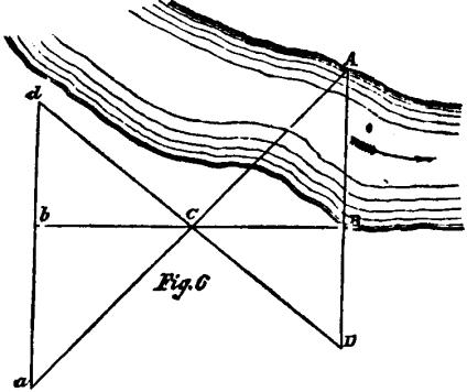 1st. The line AB (the distance to
be determined) is extended upon the bank to D, from which point, after
having marked it, lay off equal distances DC and Cd; produce BC
to b, making Cb= CB; then extend the line db until
it intersects the prolongation of the line CA at a. The distance
ab is equal to AB or the width of the river.
1st. The line AB (the distance to
be determined) is extended upon the bank to D, from which point, after
having marked it, lay off equal distances DC and Cd; produce BC
to b, making Cb= CB; then extend the line db until
it intersects the prolongation of the line CA at a. The distance
ab is equal to AB or the width of the river.
2d. Lay off any convenient distance, BC, perpendicular to AB, erect a perpendicular DC to AC, note the point D where it intersects AB pro-
BC2
duced; measure BD; then AB=BD.*
37. How can the breadth of a river be ascertained by the means of the peak of a cap, or cocked hat?
*The 2d method was suggested to me by Captain Vogdes, 1st Artillery, U.S. Army.
MISCELLANEOUS.
Place yourself at the edge of one bank and lower the peak of the cap, or point of the hat, till the edge cut the other bank, then steady your head, by placing your hand under your chin, and turn gently around to some level spot of ground on your own side of the river, and observe where your peak or point of your hat again meets the ground; measure this distance, which will be nearly the breadth of the river.
38. How do you ascertain the distance of an object by means of the tangent scale of a gun, the height of the object at the required distance being known?
Direct the line of metal of the gun on the top the object; then raise the tangent slide till the topof it and notch on the muzzle are in line with the foot of the object, and note what length of scale is required; then by similar triangles, as the length of the raised part of the tangent scale is to the length of the gun, so is the height of the distant object to the distance required.
39. What composition may be used for greasing the axle-trees of artillery cartridges?
Hog’s lard softened by working it. If this cannot be procured, tallow or other grease may be used; if hard, is should be melted with fish-oil.
40. What is the simplest method of bursting open strong gates?
Suspend a bag of gunpowder containing 50 or 60lbs. near the middle of the gate, upon a nail or gimlet, having a small piece of port-fire inserted at the bottom, and well secured with twine.
41. What is the length of a pendulum to vibrate seconds, half and quarter seconds, respectively?
HAND-BOOK OF ARTILLERY.
Seconds, 39.1 inches; half-seconds, 9.8 inches; and quarter-seconds, 245 inches.
42. Give a formula for determining the length of the seconds pendulum in any latitude.
l= 1/9.8696044 [32.1803 feet—0.O8221 cos. 2 1st.]
43. How are the times of a single oscillation of two pendulums to each other?
As the square-roots of their lengths.
44. Repeat the table of measures.
10
tenths
- -
-
- 1 inch
4 inches
-
-
-
-
1 hand
12 inches - - . - - 1 foot
28 inches - - - - - - 1 pace
8 feet- - . . - - 1 yard
2 yards - - - - - - 1 fathom
220 yards . - - - - 1 furlong
1760 yards - - - - - 1 mile
45. Repeat the table of avoirdupois weight.
27.34878 Troy grains - - - 1 dram
16 drains - - - - - 1 ounce
16 ounces -- . . - - 1 pound
28 pounds - - - - - 1 quarter
4 qrs. or 112 lbs. - - - - 1 cwt.
20 cwt . . - - - - 1 ton
In some of our States the ton Is estimated at 2000 lbs.
46. What is the force of gravity?
It is that force of attraction exerted by the earth upon all particles of matter, which tends to urge them towards its centre.
47. What is the specific gravity of a body?
The ratio of the weight of a body to that of an equal volume of some other body assumed as a
MISCELLANEOUS.
standard, usually pure distilled water at a certain temperature.
48. What is the law of descent of falling bodies?
The spaces fallen through from the commencement of the descent are proportional to the squares the times elapsed.
49. What compositions are made use of for preserving iron cannon?
1. Black lead, pulverized . . . . . 12
Red lead. . . . - - - 12
Litharge - - - - - - - - 5
Lampblack - - - - 5
Linseed oil - - - - . 66
Boil it gently about twenty minutes, during which time it must be constantly stirred.
2. Umber, ground - . - 3.75
Gum shellac, pulverized - - - 3.75
Ivory black . - - - 3.75
Litharge- - - - . 3.75
Linseed oil - - - - 73
Spirits of turpentine - - - 7.25
The oil must be first boiled half an hour; the mixture is then boiled24 hours, poured off from the sediment, and put in jugs, corked.
3. Coal tar, (of good quality) - - - 2 gals.
Spirits of turpentine - - - - - 1 pint
In applying lacker, the surface of the iron must first cleaned with a scraper and a wire brush, if necessary, and the lacker applied hot, in two thin coats, with a paint brush. It is better to do it in summer. Old lacker should be removed with a scraper, or by scouring, and not by heating the guns or balls, by which the metal is injured.
HAND-BOOK OF ARTILLERY.
About 5 gallons of lacker are required for 100 field-guns and 1000 shot; about 1 quart for a seacoast gun. Before the lacker is applied, every particle of rust is removed from the gun, and the vent cleared out.
50. How many gallons does a cubic foot contain?
7.48 gallons
51. What is the weight of a gallon of distilled water!
At the maximum density (390.8 Fahr.), the barometer being at 30 inches, it weighs 8.33888 avoirdupois pounds, or 58373 Troy grains.
52. What are the different lengths of plummets for regulating the march of infantry?
Common time 90 steps in a minute, 17.37 inches.
QuIcktime
110
“
“
‘ 11.6 “
Double quick.
140
“
“
“
7.18 “
53. How is a plummet made?
By means of a musket ball, suspended by a silk string, upon which the required lengths are marked; the length is measured from the point of suspension to the centre of the ball.
54. Explain how to embark and disembark artillery and its stores.
1. Divide the total quantity to be transported among the vessels, and place in each vessel every thing necessary for the service required at the moment of disembarkation, so that there will be no inconvenience should other vessels be delayed.
2. If a siege is to be undertaken, place in each vessel with each piece of artillery its implements, ammunition, and the carriages necessary to trans-
MISCELLANEOUS.
port the whole or a part;the platforms, tools, instruments, and materials for constructing batteries, skids, rollers, scantling, and plank.
3. If a particular caliber of gun is necessary for any operation, do not place all of one kind in one vessel, to avoid being entirely deprived of them by any accident.
4. Dismount the carriages, wagons, and limbers, by taking off the wheels and boxes, and, if absolutely necessary, the axletrees. Place in the boxes the linch-pins, washers, &c., with the tools required for putting the carriage together again. Number each carriage, and mark each detached article with the number of the carriage to which it belongs.
5. The contents of each box, barrel, or bundle, should be marked distinctly upon it. The boxes should be made small for the convenience of handling, and have rope handlesto lift them by.
6. Place the heaviest articles below beginning with the shot and shells (empty,) then the guns, platforms, carriageslimbers, ammunition boxes, &c.; boxes of small arms and ammunition in the driest and least exposed part of the vessel. Articles required tobe disembarked first shouldbe put in last, or so placed that they can be readily got at.
If the disembarkation is to be performed in front of the enemy, some of the field-pieces should be so placed that they canbe disembarked immediately, with their carriages, implements, and ammunition; also the tools andmaterials for throwing up temporary intrenchments on landing.
7. Some vessels should be laden solely with
HAND-BOOK 0F ARTILLERY.
such powder and ammunition as may not be required for the immediate service of the pieces.
8. On a smooth, sandy beach, heavy pieces, &e., may be landed by rolling them overboard as soon as the boats ground, and hauling them up with sling-carts.
SERVING AND WORKING HEAVY ARTILLERY.
SERVING AND WORKING HEAVY ARTILLERY.
General Directions.
Formation of a Company into Detachments.
A company being in one rank faced to the right, and told off into the number of cannoneers required for the pieces, is formed into detachments by the following commands:
I. In two ranks form detachments.
2. MARCH.
At the first command, tho leading man of each detachment faces to the front, and at the second command, the other cannoneers step off together The second man, counting from the right, in each detachment, places himself behind the first, and faces to the front. The two following men will, in like manner, on closing up, form the next file, and so on. The sergeants, according to seniority, take charge of the detachments from right, to left, and tell oft their detachments. Each of these sergeants is designated chief of piece.
HAND-BOOK OF ARTILLERY.
Telling Off the Detachments.
1. The odd numbers form the rear, and the even numbers and the gunner, the front rank. The right file is numbered 1 and 2; the next file 3 and 4; the gunner is uncovered, and on the left of No. 4; and on his left are as many files as are required, numbered 5 and 6, 7 and 8, &c.
The March to the Battery.
2. The instructor wheels the detachments into column, or faces them by a flank either to the right or left; to the right, if he is to approach the battery on the left; and to the left, if he is to approach the battery on the right.
In column, the chief of piece is two paces in front of the centre of his detachment; faced by a flank, he is at the side of the leading front rank man. When the detachments arrive at the distance of four yards from the left or right of the battery, the instructor commands:
DETACHMENTS OPPOSITE YOUR PIECES.
As each detachment arrives in rear of its piece, it is halted by its chief of piece, and wheeled into line or faced to the front, four yards in rear of the platform, its centre in line with the axis. The chief of piece posts himself on the right of his detachment.
To Cause the Cannoneers to Take their Posts.
3. The instructor commands:
1. Detachments to your posts.
2. MARCH.
SERVING AND WORKING HEAVY ARTILLERY.
Each detachment at the first command is faced to the right by the chief of piece, and at the second command files to the left, the two ranks separating; the rear rank marching to the right of the piece, and the front rank to the left. As each man arrives at, his post, he halts and faces the piece; Nos. 1 and 2 one yard from the epaulment, parapet, or scarp, their breasts eighteen inches outside the wheels of the carriage or checks of the mortar bed; and the remaining numbers and the gunner dressing respectively on Nos. 1 and 2, at intervals of one yard, except that, between Nos. 3 and 5, there is an interval of two yards. With the mortar, Nos. I and 2 are opposite the front manoeuvring bolts, and Nos. 3 and 4 opposite those in rear. The chief of the piece, while at the battery, will generally be one yard outside the cannoneers of the left facing the piece, and two yards in rear of the platform or rearmost part of the carriage.
To Allow the Detachment to Rest.
4. The instructor commands:
In place—REST, or REST.
The cannoneers lay down their handspikes. In the first case the men remain at their posts ; in the second case, they may leave their posts, but must remain near the piece.
To Resume the Exercise.
5. The instructor commands
ATTENTION DETACHMENTS.
All resume their posts and handspikes.
HAND-BOOK OF ARTILLERY.
To Change Posts.
6. The instructor commands:
1. Change Posts.
2. MARCH.
3. CALL OFF.
At the first command the cannoneers lay down their handspikes; place their equipments on the
|
Part. |
of the carriage nearest them, and face to their I At the next command, they step off in double-quick time, each advancing one post; No. 2 taking that of No 1. On arriving at their new posts they face the piece and equip themselves.
To Leave the Battery.
7. The instructor commands:
1. Detachments rear.
2. MARCH.
The chief of piece faces the detachment to the rear at the first command, and at the second it marches to the rear, the left cannoneers closing on those of the right files to the right, and is halted and faced to the front by the chief of the piece s4 as to bring its centre opposite the middle of the platform and four yards in rear of it.
SERVING AND WORKING HEAVY ARTILLERY,
Service of a Gun mounted on a Siege
Carriage.
Seven men arc necessary; one gunner and six other cannoneers.
8. The implements, &c, are arranged as follows:
Handspikes—three on each side of the carriage, leaning against the epaulment, in line with the cannoneers.
Sponge, Rammer—one yard behind, and parallel to the line of caunoneers of the right, the sponge uppermost, the sponge and rammer-heads turned from the epaulment and supported on a prop.
Pass-bos—againstthe epaulment, outside the pile of balls.
Tube-pouch—containing friction tubes and the lanyard, which Is wound upon its handle. Suspended from the cascable.
Gunner’s-pouch——containing the gunner’s level, breech-sight, finger-stall, priming wire, gimlet, vent-punch, and chalk. Suspended from the cascable.
Chocks—oneon each side of the piece, near the ends of the hurter.
Vent-cover—covering the vent.
Tompion—inthe muzzle.
Broom—leaning against the epaulment., outside of the pile of balls.
There should be one gunner’s level, two vent-
HAND-BOOK OF ARTILLERY.
punches, one worm, one ladle, and one wrench to a battery not exceeding six pieces.
The balls are piled on the left of the piece near the epaulment, and close to the edge of the platform.
The wads are placed between the epaulment and the balls, partly resting on them.
To Cause the Implements to be Distributed.
The instructor commands:
TAKE IMPLEMENTS.
9.The gunner steps to the cascable; takes off the vent-cover, handing it to No. 2 to place against the epaulment, outside the pass-box; gives the tube-pouch to No. 3; equips himself with his own pouch and the finger-stall, wearing the latter on the second finger of the left hand; levels the piece by means of the elevating-screw; applies his level to ascertain the highest points of the base—ring and swell of the muzzle, which he marks with chalk, and resumes his post.
No. 3 equips himself with the tube-pouch. Nos. 1 and 2, after passing two handspikes each to Nos. 3 and 4, take each one for himself. Nos. 5 and 8 receive theirs from Nos. 3 and 4.
10. The handspike is held in both hands, the hand nearest the epaulment grasping it near the small end and at the height of the shoulder, back of the hand down, elbow touching the body; the other hand back up, the arm extended naturally; the butt of the handspike upon the platform, on the side farthest from the epaulment, and six inches in advance of the alignment.
11. When the cannoneer lays down his hand-
SERVING AND WORKING HEAVY ARTILLERY.
spike, he places it directly before him, about six inches in front of and parallel to the alignment, the small end toward the epaulment; and whenever he thus lays it down for the discharge of any particular duty, he will take it up on returning to his post after having completed that duty.
The Service of the Piece is Executed as follows:
The instructor commands:
1. FROM BATTERY.
12. The gunner moves two paces to his right. Nos. 1, 2, 3, 4, 5, and 6, facing from the epaulment, embar: Nos. 1 and 2 under the front of the wheels; Nos. 3 and 4 through the rear spokes of the wheels near the felly, under and perpendicular to the cheeks; and Nos. 5 and 6 under the manoeuvring bolts. When all are ready, the gunner gives the command HEAVE, which will be repeated as often as may be necessary. He sees that Nos. 5 and 6 guide the trail in prolongation of the direction of the embrasure, and as soon as the face of the piece is about one yard from the epaulment, commands HALT, at which all unbar and resume their posts. Nos, I and 2 chock the wheels.
2. Load by detail—LOAD.
13. Nos. 1, 2, and 4 lay down their handspikes. No. 2 takes out the tompion, and places it near the vent-cover. No. 1 faces once and a half to his left; steps over the sponge and rammer; faces to the piece; takes the sponge in both hands, the backs down, the right hand three feet from the sponge-head, the left hand eighteen inches from it; returns to the piece, enter-
HAND-BOOK OF ARTILLERY
the staff in the embrasure; places the left foot way between the wheel and the face of the piece, in line with the latter; breaks to the right with the right foot, the heels on a line parallel to the piece, the left leg straightened, the right knee bent, the body erect upon the haunches, and rests the end of the sponge in the muzzle, the staff in the prolongation of the bore, supported by the right hand, the right arm extended, the left hand flat against the side of the thigh. No. 2 steps to the muzzle, and occupies a position on the left of the piece corresponding to that of No. 1 on its right. He seizes the staff with the left hand, back down, near &o and outside the hand of No. I. No. 3 facing the epaulment, embars under the breech, and maintains the piece in a convenient position for the insertion of the sponge, until the gunner signals to him to unbar, lie then lays down his handspike; steps over the rammer, and seizes the staff as prescribed for the sponge; and stands ready to exchange with No. 1. No. 4 takes the pass-box and goes for a cartridge; returns and stations himself, fee the piece, about eighteen inches to the rear and right of No. 2. The gunner places himself near the stock, his left foot advanced; closes the vent with the second finger of the left hand, bending forward to cover himself by the breech; turns the elevating screw with the right hand to adjust the muzzle conveniently for loading; and makes a signal to No. 3 to unbar. In the mean time, Nos. 1 and 2, at the words ONE—TWO—THREE, &c., insert the sponge by the following motions: 1st Motion They insert the sponge as far as the hand of No. I, bodies erect, shoulders square. 2d Motion. They
SERVING AND WORKING HEAVY ARTILLERY
slide the hands along the staff, and seize it at arm’s length. 3d Motion. They repeat the flrst motion. 4th Motion. They repeat the second motion. 5th Motion -They force the sponge to the bottom of the bore. No. 1 then replaces his left hand on the staff, back up and six inches nearer the muzzle than his right. No.2 places his right hand, back up, between the hands of No. 1. Should the sponge or the rammer reach the bottom of the bore at the third or fourth motion, then what is prescribed for the fifth motion will be performed at the third or fourth. The knee on the side toward which the body is to be inclined is always bent, the other straightened; and the weight of the body added as much as possible to the effort exerted by the arms.
3. SPONGE.
14. Nos. I end 2 pressing the sponge firmly against the bottom of the bore, turn it three times from right to left, and three times from left to right; replace the hands on the thighs, and withdraw the sponge by motions contrary to those for inserting it. When the sponge fits tight, Nos. 1 and 2 may use both hands. No. 2 quits the staff, and turning toward No. 4, receives from him the cartridge, taking it in both hands, backs down, and introduces it bottom foremost into the bore, seams to the sides; he then grasps the rammer in the way prescribed for the sponge. No. I rising upon time right leg, and turning to his left, passes the sponge above the rammer to No. 3 with is left hand, amid receiving the rammer with the right, presents it as prescribed for the sponge, except that he rests the rammer-head against the
HAND-BOOK OF ARTILLERY.
right side of the face of the piece. No. 3, as soon as the sponge is withdrawn, passes the rammer under the sponge into the embrasure with the right hand, receives the sponge from No. 1 with the left, replaces it upon the prop, and resumes his post. No.4, setting down the pass-box, takes out the cartridge and presents it in both hands to No. 2, the choke to the front; returns the pass-box to its place; and picks up a ball, and afterward a wad, if required. Nos. I and 2 force the cartridge home by the same motions as in case of the sponge.
4. RAM.
15. Nos. 1 and 2, drawing out the rammer to the full extent of their arms, ram with a single stroke. No. 2 quits the staff, and turning toward No. 4, receives from him the ball, and a wad if required, whilst No. 1 throws out the rammer, and holds the head against the right side of the thee of the piece. No. 2, introducing the ball and wad into the bore, seizes the staff with the left hand, back down. No. 4 then resumes his post. Nos. 1 and 2 force the ball and wad home together by the same motions, and ram in the same manner as prescribed for the cartridge. No. 2 quits the rammer; sweep; if necessary, the platform on his side; passes the broom to No. 1; and resumes his post. No. 1 throws out the rammer, and replaces it on the prop under the sponge; sweeps his side of the platform, if necessary, and resumes his post. The gunner pricks the cartridge, leaves the priming wire in the vent, and resumes his post; and, if firing beyond point blank, adjusts the breech-sight to the distance.
SERVING AND WORKING HEAVY ARTILLERY.
5. IN BATTERY.
16. Nos. 1 and 2 unchock the wheels, and with Nos. 3, 4, 5, and 6, all facing toward the epaulment, embar: Nos. 1 and 2 through the front spokes of the wheels near the felly, under and perpendicular to the cheeks; Nos. 3 and 4 under the rear of the wheels; and Nos. 5 and 6 under the manoeuvring bolts. When all are ready, the gunner commands HEAVE, and the piece is run into battery; Nos. 5 and 6 taking care to guide the chase into the middle of the embrasure. As soon as the wheels touch the hurter, he commands HALT. All unbar, and Nos. 1, 2, 3, and 4 resume their posts.
6. POINT.
17. No. 3 lays down his handspike; passes the hook of the lanyard through the eye of a tube from front to rear, and holds the handle of the lanyard in the right hand, the hook between the thumb and forefinger. Nos. 5 and 6 embar under and perpendicularly to the trail near the manoeuvring-bolts. The gunner, placing himself at the stock, as at the command LOAD, withdraws the priming wire, and, assisted by Nos. 5 and 6, gives the direction; causing the trail to be moved by commanding LEFT, or RIGHT, tapping, at the same time, on the right of the breech for No. 5 to move the trail to the left, or on the left side for No. 6 to move it to the right, he then places the centre of the breech-sight accurately upon the chalk mark on the base-ring, and by the elevating-screw, gives the proper elevation, rectifying the direction,
HAND-BOOK OF ARTILLERY.
if necessary. The moment the piece is pointed, he rises on his left leg, and gives the word READY, signaling with both hands, at which Nos. 5 and 6 unbar, and resume their posts; takes the breech-sight in his left hand, and goes to the windward to watch the shot. No. 3 inserts the tube into the vent; drops the handle, allowing the lanyard to uncoil as he steps back to his post, holding it slightly stretched with his right hand, the cord passing between the fingers, back of the hand up, and breaks to the rear a full pace with the left foot, the left hand against the thigh. At the word READY, Nos. 1 and 2 take up the chocks, and breaking off with the feet farthest from the epaulment, stand ready to chock the wheels.
7. Number one (or the like)—FIRE.
18. No. 3 pulls smartly on the lanyard. Immediately after the discharge of the piece, Nos. 1 and 2 chock the wheels, and resume the erect position. No. 3 resumes the erect position, and rewinds the lanyard, returning it, if dry, to the tube-pouch. The gunner, having observed the effect of the shot, returns to his post.
To Load for Action.
19. The instructor commands:
Load for action—LOAD.
The piece is run from battery, loaded, run into battery, pointed, and prepared for firing by the following commands from the gunner: FR0M BATTERY—LOAD—IN BATTERY—POINT—READY. At the command or signal from the instructor to
SERVING AND WORKING HEAVY ARTILLERY.
commence filing, the gunner gives the command FiRE, and continues the action until the instructor commands CEASE FIRING.
To Secure Piece, and Replace Instruments.
20. The instructor commands:
1. SECURE PIECE.
No. 2 replaces the tompion in the muzzle. The gunner puts on the vent-cover, which he receives from No. 2, and depresses the muzzle.
2. REPLACE IMPLEMENTS.
Nos. 1 and 2 replace the handspikes against the epaulment, those of Nos. 3, 4, 5, and 8 being passed to them by Nos. 3 and 4. The gunner hangs the pouches upon the cascable.
To Serve the Piece with Reduced Numbers.
21. The smallest number of men with which siege guns can be served with facility is five. It may be necessary to employ a less number.
With four men. They will be told off as gunner, and Nos. 1, 2, and 3. No. 2 will, in addition to his own duties, perform those of No. 4.
With three men. They will be told off as gunner, and Nos. 1 and 2. No. 1, in addition to his own, performs the duties of No. 3, and No. 2 those of No. 4as in the preceding case. When No. 2 serves ammunition, he goes for the cartridge, and places the pass-box behind his post before he assists No. 1 to sponge.
HAND-BOOK OF ARTILLERY.
Service of a Gun mounted on a Barbette
Carriage.
The service of this gun differs but little from that of a siege gun. Five men are necessary: one gunner and four other cannoneers.
22. The implements, &c., are the same as proscribed for the siege gun, No. 8, except that two handspikes are omitted, and a budge-barrel is employed to hold the cartridges, which is placed at some safe position in rear. The chocks are at the foot of the parapet inside the handspikes.
To Cause the Implements to be Distributed.
The instructor commands:
TAKE IMPLEMENTS.
23. Executed as in siege gun, No. 9, with the following modifications: The gunner mount. upon the tongue, and is assisted by No. 2 in marking the line of metal.
The Service of the Piece is executed as follows:
The instructor commands:
1. FROM BATTERY.
24. The gunner moves two paces to his right. Nos. 1, 2, 3, and 4 facing from the parapet, embar near the tire: Nos. 1 and 2.—first placing the
SERVING AND WORKING HEAVY ARTILLERY.
chocks on the rails in front of the rollers—through the front spokes of the wheels, over the front manoeuvring bolts; and Nos. 3 and 4 through the rear spoke, under the rear manoeuvring bolts. In case there are no rear manoeuvring bolts, Nos. 3 and 4 embar under the braces, near the manoeuvring staples. The execution of the remainder is the same as in case of the siege gun, No. 12.
2. Load by detail—LOAD.
25. Executed as in siege gun, No. 13, with the following modifications: No. 3 does not embar under the breech, but lays down his handspike at the same time with the other numbers, and as soon as the sponge is inserted in the bore, steps over the rammer, and seizing the staff in the prescribed manner, returns to his post and stands ready to exchange with No. 1. The gunner mounts upon the tongue of the chassis, placing the left foot about six inches from the rear transom (if the gun carriage, and breaks well to the rear with the right foot, the toe to the right. Nos. 1 and 2 p lace the feet nearest the carriage on the rails of the chassis in line with the face of the piece; the other feet are in the most convenient position on the parapet. The execution of the remainder is the same as in case of the siege gun, No. 13.
3. SPONGE.
Executed as in siege gun, No. 14.
4. RAM.
Executed as in siege gun, No. 15.
5. IN BATTERY.
26. Nos. 1 and 2 unchock the rollers, and
HAND-BOOK OF ARTILLERY.
with Nos. 3 and 4, all facing toward the parapet, embar: Nos. 1 and 2 through the front spokes of the wheels, near the tire, under the manoeuvring bolts; and Nos. 3 and 4 under the braces near the manoeuvring staples. When all are ready, the gunner commands HEAVE, and the piece is run into battery, the gunner following up the movement. He commands HALT, when the rollers touch the hurters, and Nos. 1, 2, 3, and 4 unbar and resume their posts.
6. POINT.
27. Executed as in siege gun, No. 17, with the following modifications: Nos. 1 and 4 go to the traverse wheels, and facing the parapet, embar under the fork-bolts or under the wheels. The gunner is assisted by No.. 1. and 4 in giving the direction, and, before dismounting from the chassis after the command READY, receives the tube from No. 3 which he inserts into the vent.
7. Number one (or the like)—FIRE.
Executed as in siege gun, No. 18.
SERVING AND WORKING HEAVY ARTILLERY.
Service of an 8-inch Sea-coast Howitzer
mounted on a Barbette Carriage.
Five men are necessary: one gunner and four other cannoneers.
28. The implements, &c., and their arrangement, are the same as for the barbette gun, substituting haversack—worn by No. 4 from the right shoulder to the left side—for pass-box.
The instruction for this piece is the same as for the barbette gun. It is loaded with a shell attached a sabot. The shell, together with the cartridge, brought up by No. 4, and is set home in the same manner as the ball, but is not rammed.
HAND-BOOK OF ARTILLERY.
Service of a 10-inch Sea-coast Howitzer
mounted on a Barbette Carriage.
29. Seven men are necessary: one gunner and six other cannoneers. The implements, &c., with the addition of one handspike, and their arrangement, are the same as prescribed for the 8-inch seacoast howitzer, No. 28. The instruction for this piece varies but slightly from that prescribed for the 8-inch sea-coast howitzer.
30. The shell is brought up in the following manner:
No. 6 takes the handspike and goes for the shell, followed by No. 5. He passes the small end of the handspike through the ring of the shell hooks, or through the loop of the rope handle; No. 5 holds the small end of the handspike with his right hand, No. 6 the butt end, No. 5 in front. They bring it up on the left of the piece, and place themselves parallel to the parapet, No. 5 behind No. 2. No. 5stepping between the parapet and the face of the piece, passes his end of the handspike to No. I, and places himself on the tongue, or on the platform, opposite the muzzle; No. 6 gives his end of the handspike to No. 2. Nos. I and 2 raise the shell until it is opposite the muzzle:
SERVING AND WORKING HEAVY ARTILLERY.
when No.6, applying his hands under it, raises the sabot and inserts it in the muzzle. No. 2 withdraws the handspike and passes it to No. 6 who replaces it. No. 5 pushesthe shell Into the muzzle and returns to his post.
HAND-BOOK OF ARTILLERY,
Service of a Gun mounted on a
Casemate Carriage.
Five men are necessary: one gunner, and four other cannoneers.
31. The implements, &c., are arranged as follows:
Truck-handspiks.—Oneon each side of the carriage, leaning against the wall, in line with the cannoneers.
Elevating-handspikes.—Oneon each side of the carriage, leaning against the wall, behind Nos. 3 and 4. These are manoeuvring handspikes.
Traversing-handspikes.—Oneon each side of the carriage, leaning against the wall, opposite the end of the tongue. These are manoeuvring handspikes.
Roller-handspike.—Leaning against the wall, behind the gunner, or laid down in the alignment; on his right.
Sponge, Rammer.—Same as in siege gun exercise, No. 8.
Pass-box.—Behind No. 4.
|
Tube-pouch. Gunner’s-pouch. Vent-cover. Tompion.
|
} |
Same as in siege gun, No. 8.
|
SERVING AND WORKING HEAVY ARTILLERY.
Chocks.—Oneon each side of the carriage, on the front transom of the chassis, handles outward.
Broom.—Leaning against the scarp wall, on the left of the piece.
Budge-Barrel.—Same as in barbette gun, No. 22.
The balls are regularly piled against the wall, behind No. 2. The wads are between the wall and the balls, partly resting on them.
To Cause the Implements to be Distributed.
The instructor commands:
TAKE IMPLEMENTS.
32. Executed as in siege gun, No. 9, with the following modifications: The gunner mounts upon the tongue; in levelling the piece, he is assisted by No. 3, and in marking the line of metal by No.
2. He then takes the roller handspike and resumes his post. His handspike is held in the right hand, the lower end on the ground in line with the toes, the arm extended naturally. Nos. 1 and 2 take the truck-handspikes with the hand farthest from the wall, and carry them to that side, holding them vertically, the lower end on the ground as in the of the roller-handspike.
The Service of the Piece is Executed as follows:
The gunner commands:
1. FROM BATTERY.
33 . The gunner embars in the left mortise of the roller. Nos. 1 and 2, facing from the scarp wall, embar in the most convenient front mor-
HAND-BOOK OF ARTILLERY.
tises of the truck-wheels, the hand farthest from the carriage at the top of the handspike, the other hand eight inches lower. Nos. 3 and 4 go to the assistance of Nos. 1 and 2, and, facing toward them, seize the handspikes with both hands between those of Nos. 1 and 2.
All being ready, the gunner presses the roller under the rear transom of the gun carriage, by bearing down on the handspike, and gives the command HEAVE. Nos. 1, 2, 3, and 4 bear upon the handspikes until they are nearly down to the rails.
The gunner then disengages the roller from under the transom, by raising his handspike, and commands UNBAR. Nos. 1 and 2 let go the handspikes with the hand nearest the carriage, and chock the wheels. Nos. 3 and 4 withdraw the handspikes and pass them to Nos. I and 2, who reinsert them in the front mortises. The gunner again bearing down on his handspike, gives the command HEAVE, and so on, until the face of the piece is about one yard from the wall, when, raising his handspike, he commands HALT, and shifts it into the right mortise of the roller. Nos. 1 and 2 chock the wheels and replace their handspikes against the wall. All resume their posts.
2. Load by detail—LOAD.
Executed as in siege gun, No. 13.
3. SPONGE.
Executed as in siege gun, No. 14.
4. RAM.
Executed as in siege gun, No. 15.
5. IN BATTERY.
34. Nos. 1 and 2 unchock the wheels, and,
SERVING AND WORKING HEAVY ARTILLERY.
facing from the scarp-wall, apply their hands to the front of the cheeks. Nos. 3 and 4, facing toward the scarp wall, lay hold of the handles. The gunner bears down carefully upon the roller-handspike, and the piece is run into battery. As coon as the wheels touch the hurters, he commands HALT. Nos. 1, 2,3, and 4 resume their posts.
6. POINT
35. Nos. 1 and 4, with the traversing-handspikes, and facing toward the scarp wall, embar under the ends of the rear transom of the chassis. No. 1, in moving from and to his post, passes on the outside of No. 3. When the elevation is given by the quoin, No. 2 takes an elevating-handspike, and embars upon the left check under the reinforce. The gunner withdraws the priming-wire, and assisted by Nos. 1 and 4, gives the direction, He then applies the breech-sight, if necessary, and points the piece; commanding LOWER, or RAISE, tapping, at the same time, on the upper side of the knob of the cascable with the left hand, and drawing out the quoin with the right, in order to elevate the piece; or tapping on the lower aide and shoving in the quoin to depress the piece. When the piece is correctly pointed, he rises on the left leg, and gives the word READY, &c., as in case of the siege gun, at which Nos. 1, 2, and 4 unbar, replace their handspikes, and resume their posts; takes the breech-sight in his left hand, and the roller-handspike in the right, and places himself to observe the effect of the shot.
(If the elevation is given by a screw, No. 3 turns its handle by direction of the gunner.)
HAND-BOOK 0F ARTILLERY.
At the word READY, the duties of No. 3 are the same as in case of the siege gun, No. 17. After Nos. 1 and 2 resume their posts, they take up the chocks, and breaking off in the usual manner, stand ready to chock the wheels.
- Number on (or the like)—FIRE.
- Executed as in siege gun, No. 18.
SERVING AND WORKING HEAVY ARTILLERY.
Service of an 8-inch Columbiad, mounted
on a Columbiad Carriage.
Five men are necessary: one gunner, and four other cannoneers.
36. The implements, &c., are arranged as follows:
Truck-handspikes.—Two on each side of the carriage, laid on the rails, one in rear of each truck-wheel.
Manoeuvring-Handspikes.—One on each side of the carriage, laid on the ground in a line with the cannoneers, opposite the traverse wheels, the small ends toward the parapet.
Elevating-bar.—Laid across the horizontal ties at the junction of the braces, handle to the left.
Sponge, Rammer.—Nearly the same as in siege gun exercise, No. 8.
Haversack.—Suspended from the knob of the cascable, instead of a pass-box.
|
Tube-pouch. Gunner’s-pouch. Vent-cover, Tompion.
|
} |
Same as in siege gun, No. 8.
|
Chocks—One on each side of the piece, laid on the front of the rails.
Broom—Leaning against the parapet, to the left of the piece.
HAND-BOOK OF ARTILLERY.
Budge-barrel.—As in barbette gun, No. 22.
To Cause. the Implements to be Distributed.
The instructor commands:
TAKE IMPLEMENT5.
37. Executed as in siege gun, No.9, with the following modifications: No. 2 places the vent-cover, when handed to him by the gunner, against the parapet, in rear of his post. The gunner gives the haversack to No.4, who wears it from the right shoulder to the left side. He levels the piece conveniently for loading, by means of the elevating-bar, and is assisted by No.2 in marking the line of sight on the piece with the chalk-line. After resuming his post, he holds the elevating-bar in his right hand. The truck-handspikes are held as in case-mate gun, No. 32.
ToCause the Service of the Piece to he Executed.
The instructor commands:
1. FORM BATTERY.
38. The gunner moves two paces to the right of his post. Nos. 1, 2, 3, and 4, facing from the parapet, place the wrenches of their handspikes on the ends of the axle-trees, the handspikes elevated about 300 to the rear, and at the word HEAVE by the gunner, bear down and throw the wheels into gear; Nos.3 and 4 then lay their handspikes on the plat- form in front of their posts. The piece is now run from battery by Nos. 1, 2, 3, and 4, precisely as in ease of the casemate gun, No. 33. At the command HALT, Nos. 1 and 2 unbar and place the wrenches of
SERVING AND WORKING HEAVY ARTILLERY.
their handspikes on the ends of the front axle-trees, and at the command OUT OF GEAR by the gunner, they throw the front wheels out of gear, lay their handspikes on the rails between the wheels, and resume their posts.
- Load by detail—LOAD.
39. Executed as in barbette gun, No. 25; No. 4 brings up a shell together with the cartridge.
- SPONGE.
Executed as in siege gun, No. 14.
- RAM.
Executed as in siege gun, No. 15, except that the shell is set carefully home, without being rammed.
5. IN BATTERY.
40. Nos. 1 and 2 unchock the wheels, and place the chocks on the horizontal ties. Nos. 1, 2, 3, and 4, facing toward the parapet, apply the wrenches of their handspikes to the ends of the axle-trees, Nos. 1 and 2 so as to throw the front wheels into gear, and Nos. 3 and 4 so as to be ready to throw the rear wheels out of gear. The gunner commands HEAVE, when Nos. 1 and 2 throw the front wheels into gear. Should the carriage run into battery too rapidly, the gunner must command REAR WHEELS OUT OF GEAR, when Nos. 3 and 4 throw the rear wheels out of gear. Nos. 3 and 4 then take a chock each, and hold it in front of the rear wheels to chock them, if the carriage runs too rapidly. If necessary, the rear wheels must be thrown alternately in and out of gear, until the head of the carriage touches the hurters. The
HAND-BOOK OF ARTILLERY.
gunner then commands OUT 0F GEAR, when all the wheels which are in gear are thrown out of gear. Nos. 1, 2, 3, and 4 resume their posts, and lay their handspikes on the platform in front of them.
8. POINT.
41. Executed as in barbette gun. No. 27, with the following modifications: No. 2 goes to the traverse wheel Instead of No. 4, and No. 4 turns the handle of the elevating screw, by direction of the gunner.
Ifs greater elevation than one notch is to be given, the gunner, by means of the elevating-bar, transfers the pawl to the proper notch, and, if necessary, Nos. 1 and 2 insert a handspike in the muzzle, to enable the gunner to free the purl from the notch.
7. Number one (or the like)—FIRE.
Executed as in siege gun, No. 18.
v
SERVING AND WORKING HEAVY ARTILLERY.
Service of a 10-Inch Columbiad, mounted
on a Columbiad Carriage.
Seven men are necessary: one gunner and six other cannoneers.
42. The implements, &c., with the addition of one manoeuvring handspike, and substituting pass-box—placed against the parapet behind No. 2—for haversack, and their arrangements are the same as in 8-inch columbiad, No. 36. The instruction for this piece differs but slightly from that for the 8-inch columbiad. The shell is brought up and inserted as prescribed in No. 30.
HAND-BOOK OF ARTILLERY.
ServIce of a 1O-inch Celumbiad, mounted
on an Iron Carriage.
Seven men are necessary: one gunner and six other cannoneers.
The piece is in battery.
The implements, &c., are arranged as follows:
Truck-handspikes.—Oneon each side of the carriage, against the parapet.
Eccentric-handspikes.—Oneon each side of the carriage, against the parapet.
Manoeuvring-handspikes.—Two on the left and one on the right side of the carriage, laid on the ground in a line with the cannoneers, opposite the traverse wheels, the small ends toward the parapet.
Elevatinq-bar.—Laid across the rear part of the gun carriage, handle to the left.
Two sponge. and one rammer—oneyard in rear of the cannoneers of the right, the sponges uppermost, the sponge and rammer heads turned from the parapet, inclined slightly from the piece, and supported on a prop.
Pass-box.—Against the parapet, behind No. 2.
|
Tube-pouch Gunner’s-pouch. Vent-cover. Tompion. |
} |
As in siege gun, No. 8.
|
Broom.—Against the parapet on the left of the piece.
SERVING AND WORKING HEAVY GUNS.
Budge-barrel.—As in barbette gun, No. 22. The shells are brought, as required, to the place prescribed for the budge-barrel.
To Cause the Implements to be Distributed.
The instructor commands:
TAKE IMPLEMENTS.
Executed as in No. 37, with the following modifications: a pass-box is used instead of a haversack; Nos. 1 and 2 take each a truck hand-spike, first passing the eccentric-handspikes to Nos. 3 and 4.
ToCause the Service of the Piece to be Executed.
The instructor commands:
1. FROM BATTERY.
The gunner moves two paces to the right of his post. Nos. 3and 4 apply the eccentric-handspikes to the ends (if the axle, the handspikes elevated about 30o to the rear, and at the word HEAVE by the gunner, bear down, and throw the wheels into gear; Nos. 1 and 2 then embar (facing from the parapet) in the most convenient mortises of the truck-wheels, and Nos. 3 and 4 insert the eccentric-handspikes into the most convenient mortises of the same wheels. Nos. 5and 6, respectively facing toward Nos. 3 and 4, seize the eccentric-handspikes as near the ends as possible with one or both hands. All being ready, the gunner gives the command HEAVE. Nos. 1,2, 3, 4, 5, and 6 act together and bear down until the eccentric handspikes are nearly down to the rails, when the
HAND-BOOK OF ARTILLERY.
gunner gives the command UNBAR, and the handspikes are then shifted to other convenient mortises by No.. 3 and 4 and 1 and 2, the latter waiting until 3 and 4 have reinserted theirs, and the same Nos. prepare to bear down as before. The gunner again gives the command HEAVE, and so on, until the face of the piece is one yard from the parapet, when he commands HALT. No.. 3 and 4 then place their handspikes on the ends of the axle, and at the command OUT OF GEAR from the gunners throw the wheels out of gear; all take their posts and lay down their handspikes in front of their alignment.
2. Load by detail—LOAD.
Executed as in barbette gun, No. 25. The shell is brought up as in No. 30.
3. SPONGE.
Executed as in siege gun, No. 14, two sponges being used, the smaller for the chamber, and the larger for the cylinder of the bore.
4. RAM.
As in No. 39.
5. IN BATTERY.
No.. 3 and 4 apply their eccentric-handspikes to the ends of the axle, and at the command HEAVE by the gunner, throw the wheels into gear, and No.. 1 and 2 insert their truck-hand-spikes into the most convenient mortise. of both wheels to start the carriage forward. The eccentric-handspikes are held firmly by No.. 3 and 4 while the piece is running into battery. In case the gun should run too rapidly, they immediately
SERVING AND WORKING HEAVY ARTILLERY.
throw the wheels out of gear. As soon as the head of the carriage touches the hurters, the eccentric and truck handspikes are laid on the platform in front of the cannoneers.
6. POINT.
Executed as in No. 41.
7. Number one (or the like)—FIRE.
Executed as in siege gun, No. 18.
In case of the 8-inch columbiad, the 32 or 42-pdr. or any gun of like weight, mounted on an iron carriage, but four men besides the gunner are required. No truck handspikes are required, the eccentric handspikes being sufficient.
At the command FROM BATTERY, Nos. 1 and 2 place themselves on the ends of the axle, and at the command HEAVE by the gunner, throw the wheels into gear. They then insert them in the most convenient front mortises and, assisted by Nos. 3 and 4, bear down at the command HEAVE by the gunner. At the command UNBAR, given by the gunner as soon as the handspikes are nearly down to the rails, Nos. 1 and 2 let go the handspikes and chock the wheels. Nos. 3 and 4 then withdraw the handspikes and pass them to Nos. 1 and 2, who reinsert them in the front mortises and the same Nos. prepare to bear down asbefore. If no chocks are used, No. 3withdraws his handspike at the command TWO, given by the gunner as soon as No. 1 has reinserted his. When the face of the piece is about one yard from the parapet, the gunner commands HALT. Nos. 1 and 2 then chock the wheels, place the handspikes on the ends of the axle, and at the com-
HAND-BOOK OF ARTILLERY.
mand OUT OF GEAR by the gunner, they throw the wheels out of gear. Or, if no chocks are used, No. 2 keeps his handspike in the mortise, and No. 1 transfers his to the end of the axle, to throw the wheel out of gear.
To bring the piece in battery, it suffices to place the wrench of but one eccentric handspike on the end of the axle, either that of No. 1 or No. 2.
The service of the 15-inch columbiad, mounted on an iron carriage, does not differ materially from that of the 10-inch, except that double the number of men are required.
SERVING AND WORKING HEAVY ARTILLERY.
Service of a 24-pdr. Howitzer, mounted
On a Flank Casemate Carriage.
Three men are necessary: one gunner and two other cannoneers.
43. The implements are arranged as follows:
Roller handspike.—Leaning against the scarp wall, behind No. 2.
Sponge and Rammer.—Leaning against the scarp wall, behind No. 1, the rammer-head upon the ground.
Haversack—Suspended from the cascable.
Tube-pouch.—Containing, in addition to friction tubes, and lanyard, a fingerstall and priming-wire. Suspended to cascable.
Vent-cover, tornpion,—sameas in siege gun, No.8.
Broom—Onthe left of piece.
Budge-barrel.—Same as in barbette gun, No. 22.
The rounds of canister are against the scarp wall, behind No. 2.
Shells, if used, are brought to the place prescribed for the budge-barre1.
To Cause the Implements to be Distributed.
The instructor commands:
TAKE IMPLEMENTS.
44. The gunner takes from the tube-pouch
HAND-BOOK OF ARTILLERY.
the priming-wire and fingerstall, wearing the latter on the second finger of the right hand; gives the tube-pouch to No. 1 and the haversack to No. 2; takes off the vent-cover and lays it against the scarp wall, outside the canisters; takes the roller handspike in his right hand and resumes his post. He holds this handspike as prescribed in casemate gun, No. 32. No. 2 wears the haversack as prescribed for No. 4 in case of the 8-inch Columbiad, No. 37.
ToCause the Service of the Piece to be Executed.
The instructor commands:
1. FROM BATTERY.
45. The gunner, embarring in the left mortise, presses the roller under the rear transom, and seizes the left handle with his left hand. No.. 1 and 2 lay hold of the manoeuvring rings and handles. All being ready, the gunner commands HEAVE, and the carriage is run to the roar until the face of the piece is about one yard from the wall, when, disengaging the roller, he commands HALT. All resume their posts.
2. Load by detail—LOAD.
46. The gunner places himself at the breech, breaks to the rear with the right foot, closes the vent with the second finger of the right hand, and manages the elevating screw with his left. No. 1, seizing the sponge-staff at its middle, brings it across his body, plants his left foot opposite the muzzle, close to the carriage, and breaks off with his right foot; at the same time dropping the sponge-staff into the left hand, back down, and ex-
serving and working heavy artillery.
tending both hands toward the ends of the staff, he brings the sponge opposite the muzzle, he then inserts it, and presses it to the bottom of the chamber with three motions. No. 2 goes for a cartridge, and returns to his post. If shells are used, he brings one up at the same time.
3. SPONGE.
47. No. 1, using both hands, sponges the chamber carefully; withdraws the sponge, pressing it against the bottom of the bore; stepping to left he turns it over, and rests the rammer-head against the right side of the face of the piece. No. introduces the cartridge in the usual manner, and No. 1 sets it home by three motions with the right hand.
4. RAM.
48. No. 1, drawing out the rammer to the full extent of his arm, rams once, and throws out the rammer, holding it with the rammer-head against the right side of the face of the piece. No. 2 introduces the canister or shell and resumes his post. No. 1 sets the canister or shell home with care, throws out the rammer, replaces it, and resumes his post. The gunner pricks, leaving the priming-wire in the vent, and resumes his post.
5. IN BATTERY.
49. All apply themselves to the carriage, as prescribed No. 45, and ease the piece into battery. As soon as it touches the hurters, the gunner commands HALT, and all resume their posts.
6. POINT.
50. No. 1 does what has been prescribed for
HAND-BOOK OF ARTILLERY.
No. 3 in siege gun, No. 17, and No. 2 traverses the chassis by hand. The gunner withdraws the priming-wire, points the piece, and gives the command READY, making a signal with both hands, at which No. 2 resumes his post; takes out the roller handspike, and resumes his post.
7. Number one (or the like)—FIRE.
No. 1 does what is prescribed for No. 3 in siege gun, No. 18.
SERVING AND WORKING HEAVY ARTILLERY.
Service of an 8-Inch Siege Howitzer, mounted
on a 24-pdr. Siege Carriage.
Five men are necessary: one gunner and four other cannoneers.
51. The implements, &c., are arranged as follows:
Handspikes.—As in No. 8, with the exception one less handspike.
Sponge and Rammer.—On props, eighteen inchesbehind, and parallel to the cannoneers of the right, the sponge-head turned toward the epaulment.
Haversack.—containingfuzes, a pair of sleeves, and a priming-wire, bent at right angles at the point, for withdrawing the cartridge used in instruction. Suspended from the cascable.
|
Tube-pouch. Gunner’s-pouch. Loading-tongs. |
} |
Asin No. 8. |
|
Quadrant. Plummet. Scraper. Wiper. Splints. |
} |
In a basket, or on a shelf against the epaulment, |
Grommet-head. —On the end of the hurter, near No.2.
|
Chocks. Vent-cover.
|
} |
Asin No. 8. |
HAND-BOOK OF ARTILLERY.
Quoin.—Under the breech.
Broom.—Leaning against the epaulment outside of the basket or shelf.
To Cause the Implements to be Distributed.
The instructor commands:
TAKE IMPLEMENTS.
52. Executed as in No. 9, with the following modifications: No. 2 places the vent-cover outside the basket; the haversack is handed to No.4 by the gunner. The gunner directs No.3 to raise the breech, to enable him to level the piece. No. 2 puts on the sleeves, which are taken out of the haversack by No. 4, who assists No. 2 to put them on. No. 4 wears the haversack from the right shoulder to the left side. Three handspikes are passed by Nos. 1 and 2 to Nos. 3 and 4. The gunner receives his from No. 4, and lays it in the alignment, the small aid toward the epaulment, and two yards to his right
To Cause the Service of the Piece to be Executed.
The instructor commands:
1. FROM BATTERY.
53. Executed as in No. 12, with the following modifications: Nos. 1, 2, 3, and 4 embar as prescribed for Nos. 3, 4, 5, and 6. The gunner commands HALT as soon as the wheels are about one yard from the epaulment.
2. Load by detail—LOAD.
54. Executed as in No. 13, with the following modifications: No. 2, after laying down
SERVING AND WORKING HEAVY ARTILLERY.
the tompion, sweeps, if necessary, his side of the platform, passes the broom to the right side ofthe piece, and resumes his post. No. 1 faces to his right and seizes the sponge-staff’ at its middle with his right hand, back up; places himself at the muzzle, forces the sponge to the bottom of the chamber, and grasps the staff with both lands. No. 3, after receiving a signal from the runner to unbar, resumes his post. No. 4 goes for a cartridge and shell, puts the former in his haversack, takes the shell in both hands, and places it on the grummet-wad, and stands, facing the piece, about 18 inches to the rear and left of No. 2. The gunner adjusts the piece at about one degree’s elevation before he signals to No. 3 to unbar.
3. SPONGE.
55. No. 1, pressing the sponge firmly against the bottom of the chamber, turns it three times from right to left, and three times from left to right, draws it out to the front of the chamber, wipes out the bore, reinserts the sponge along the upper side of the bore as far as the chamber, draws it entirely out, pressing it upon the lower side of the bore, turns the sponge over toward the embrasure, and presents the rammer-head against the right side of the face of the piece, holding the staff in both hands, backs down. No. 2, as soon as the sponging is completed, takes the tongs and occupies a position at the muzzle, corresponding to that prescribed for No. 1 on the right, turns to his left on the right heel, advancing the left foot, and presents the tongs in both hands, the left hand nearest the body, the tongs opened, their legs in
HAND-BOOK OF ARTILLERY.
the same vertical plane. No. 4 takes the cartridge out of his haversack, and inserts it as far as its middle in the tongs, choke foremost, the seam downward, inserts the fuze into the fuze plug of the shell, scrapes its end, and takes up the wiper. No. 2, having received the cartridge in the tongs, makes a pace and a half to his right on his right heel, and breaks off’ with his left foot, places his right hand against the head of the left cheek of the carriage, and with the left hand introduces the cartridge into the chamber, keeping the legs of the tongs in a vertical plane, then slightly withdrawing and closing the tongs, he presses them against the end of the cartridge, and shoves it home. Withdrawing the tongs, he makes a pace and a half to his left on the right heel, and enters the hooks of the tongs into the ears of the shell, which he lifts and holds about two feet from the ground, whilst No. 4 wipes it; No. 1, as soon as the tongs are withdrawn, inserts the rammer, and holds its head against the cartridge, the staff in the axis of the piece.
4. RAM.
56. No. 1 presses firmly upon the cartridge, throws out the rammer, and places it upon the prop.; sweeps, if necessary, his side of the platform; passes the broom to the left side of the piece, and resumes his post. No. 2 introduces the shell, and shoves it home in a manner similar to that prescribed for the cartridge, withdraws the hooks, and sees that the fuze is in the axis of the piece. If the piece is to be fired horizontally, or at an angle of depression, No. 4, after replacing the wiper, hands a splint to No. 2, and resumes his
![]()
SERVING AND WORKING HEAVY ARTILLERY.
post. No. 2, with his left hand, presses the splint under the shell, replaces the tongs and broom, and resumes his post. The gunner pricks, leaving the priming-wire in the vent, and resumes his post.
5. IN BATTERY.
Executed as in No. 16, with the following modification: the gunner, before giving the command HEAVE, embars under one of the manoeuvring bolts.
6. POINT.
57. Executed as in No. 17, with the following modifications: Nos. 1 and 4 perform what is prescribed for Nos. 5 and 6. No. 2, facing toward the epauIment, embars under the breech or cascable, lowers or elevates it at the command of the gunner. When he gives the word READY, Nos. 1, and 4 unbar and resume their posts.
7. Number one (or the like)—FIRE.
Executed as in No. 18.
To Unload.
58. The piece being in battery, the instructor directs No. 2 to take out the shell and cartridge. No. 3 raises the breech until the shell rolls to the muzzle. No. 4 carries them to their place in rear of the piece.
To Scrape the Piece.
59. The piece is first moved from battery, and the instructor then commands: SCRAI’E THE PIECE. Nos. 1 and 2 lay down their handspikes, No. 2 takes the scraper and wiper, giving the latter to
HAND-BOOK 0F ARTILLERY.
No. I, thoroughly scrapes the chamber and bore, draws out the scrapings with the spoon, returns the scraper to its place, and resumes his post. No. 1, enveloping the sponge-head in the wiper, wipes out the bore, and returns the wiper to No. 2, who replaces it, puts the sponge upon the props, and resumes his post.
SERVING AND WORKING HEAVY ARTILLERY.
Service of a 10-inch Siege Mortar.
Five men are necessary: one gunner and four other cannoneers.
60. The implements, &c., are arranged as follows:
Handspikes.—Twoagainst each cheek, leaning upon the four manoeuvring bolts, the small end toward the epaulment, the ends of the front hand-spikes even with the front of the cheeks.
Haversack.—Containingfuzes, and a pair of sleeves. Attached to the tompion, and lying upon the mortar.
Tube-pouch.—Containingthe priming-wire, friction tubes, and the lanyard, wound in St. Andrew’s cross upon its handle. Attached to the tompion, and lying upon the mortar.
Gunner’s-pouch .—Containing thegunner’s level, gimlet, vent-punch, and chalk. Attached to the tompion, and lying upon the mortar.
Quadrant, Plummet, Pointing-Cord, Scraper, Wiper, Shell-hooks.—Ina basket, between the cheeks of the mortar bed.
Tompion.—Inthe muzzle.
Quoin.—Under the mortar, upon the bolster, its handle to t.he left.
Pointing-stakes, Maul, Broom.—With the basket.
HAND-BOOK OF ARTILLERY.
To the same battery there should be one hammer-wrench.
To Cause the Pointing Stakes to be Established
in Position.
The instructor commands:
PLANT THE POINTING-STAKES.
61. The gunner, assisted by Nos. I and 2, plants the stakes as explained in Part II, Section 2. No. 1, having driven the pointing-stakes, drives another stake one yard behind his post, for holding the wiper, and replaces the maul near the basket. The gunner lays the slack of the pointing-cord at the foot of the epaulment, leaving the plummet at the stake in rear of the piece. All then resume their posts.
To Cause the Implements to be Distributed.
The instructor commands:
TAKE IMPLEMENTS.
62. The gunner steps to the front of the piece, gives to No. 1 the sleeves and the wiper; to No.2 the basket and maul; to No. 3 the tube-pouch and broom; and to No. 4 the haversack; equips himself with the gunner’s-pouch, applies his level to ascertain the line of metal, which he marks with chalk, and resumes his post. No. 1 hangs the wiper to the stake behind his post, and, assisted by No. 3, puts on the sleeves. No.2 removes the tompion, which he places with the basket and maul one yard behind him, and lays the shell hooks on the ground between himself and the basket. No. 3 lays the broom behind him, and equips himself with the
SERVING AND WORKING HEAVY ARTILLERY.
tube-pouch. No. 4 wears the haversack from the shoulder to the left side. All take their handspikes. These are held as in No 10, and when laid down they are returned, except in one case, to their places on the manoeuvring bolts.
To Cause the Service of the Piece to be Executed. The instructor commands:
1. IN BATTERY.
3. The gunner, making a half face to his right, steps off, left foot first, and places himself two paces in rear of the platform, facing the piece. Nos. 1, 2, 3, and 4, facing the epaulment, embar; Nos. 1 and 2 under the front manoeuvring bolts, and Nos. 3 and 4 under those in rear, engaging the butts of their handspikes about three inches. All being ready, the gunner commands HEAVE, which will be repeated until the piece is on the middle of the platform, when he commands HALT, at which all unbar, and resume their posts.
2. Load by detail—LOAD.
Nos. 1, 3, and 4 lay down their handspikes. The gunner, taking the scraper, places himself in front of the muzzle, and scrapes the bore, draws out the scrapings with the spoon, returns the scraper to the basket, and again places himself at the muzzle, one yard in front. No. 1, turning to his right, takes the wiper with the right hand, faces to his left, and placing the left foot near the manoeuvring bolt, the right in front of the muzzle, and the left hand upon the face of the piece, wipes out the bore, and resumes his post. No. 3, as soon as the piece is wiped, clears the vent
HAND-BOOK OF ARTILLERY.
with the priming-wire, sweeps the platform, if necessary, and resumes his post and handspike. Nos. 2 and 4, facing to their right—No. 2 holding his handspike at the middle, under his left arm, butt-end to the front, and taking the shell-hooks in his right hand—go for a cartridge and shell. While No. 4 is getting the cartridge, No. 2 inserts the shell-hooks into the ears of a shell, and passes the small end of the handspike through the ring. In carrying the shell, they hold the handspike in their right hands, No. 4 at the small end, and in advance of No.2. Passing by the left of the piece, between the gunner and the muzzle, they rest the shell upon the platform, against the middle of the transom. No. 1, first placing the wiper upon the handspike, receives its small end from No. 4, who then gives the cartridge to the gunner. The gunner, advancing the left foot, places his left hand on the face of the piece, introduces the cartridge into the mouth of the chamber with the right hand, and carefully pours in the powder, returns the bag to No. 4, and spreads the powder evenly over the bottom of the chamber. If firing with paper fuzes, he receives one from No. 4, and inserts it in the fuze plug. No. 4 returns the cartridge bag to the haversack, and takes the wiper. Nos. 1 and 2 raise the shell, and hold it about a foot from the ground, while No. 4 wipes it; they then lift it into the muzzle. The gunner steps forward, and with his left hand over the handspike, the right hand under and nearer to it, seizes the shell hooks, and assists in lowering the shell gently into its place. No. 2 then withdraws the handspike from the ring, and resumes his post. No. 1 takes up his handspike.
![]()
Serving and working heavy artillery.
gunner sees that the fuze is in the axis of the piece, and throws the shell hooks to their place behind No. 2; if firing with wooden fuzes, he uncaps the fuze. No. 4, after wiping the shell, returns the wiper to its place, lays the slack of the pointing cord over the left manoeuvring bolts, its end at the rear pointing stakes, and resumes his post and handspike.
3. POINT.
64. Nos. 1 and 2, facing toward the epaulnent, embar upon the bolster, under and perpendicularly to the piece. The gunner applies the quadrant to the left side of the face of the piece with the left hand, and moves the quoin with the right, giving the command RAISE, or LOWER, until the piece is at the required elevation—usually 45o Returning the quadrant to the basket—Nos. 1 and 2 at the same time unbarring and resuming their posts—he places himself behind the rear pointing stake, and holding the pointing cord in the left hand and the plummet in the right, gives he direction, commanding MORTAR LEFT, MORTAR RIGHT, MUZZLE LEFT, MUZZLE RIGHT, TRAIL LEFT, TRAIL RIGHT, according to circumstances.
To throw the mortar to the left.—Nos. 2 and 4, facing each other, embar under the manoeuvring boIts. Nos. 1 and 3, facing the epaulment, embar under the notches near them. When all are ready, the gunner gives the commands HEAVE—STEADY. The cannoneers remain embarred until he gives some other command, or makes the signal to unbar.
To throw the mortar to the right.—Nos. I and 3 embar under the manoeuvring bolts, and Nos. 2 and 4 under the notches.
HAND-BOOK OF ARTILLERY.
To throw the muzzle to the left.—Nos. 1 and 3, facing toward the epaulment, embar under the front notches; No. 1 under the inside of the left notch.
To throw the trail to the left—Nos. 1 and 3, facing toward the epaulment, embar under the rear notches; No. 3 under the inside of the left notch.
The muzzle or trail is thrown to the right, in a similar manner to the preceding, by Nos. 2 and 4.
85. The direction having been given, the gunner gives the word READY, and makes a signal with both hands, leaves the plummet at the rear stake, returns the pointing cord to the foot of the epaulment, and goes to observe the effect of the shot. Nos. 1, 2, and 4 taking their handspikes, go four yards in rear of the platform and face to the front, No. 4 between Nos. I and 2, their handspikes held erect by the right side, the right arm extended naturally. No. 3 lays down his handspike six inches in his front, parallel to the edge of the platform, and makes ready a friction tube, as in No. 17; advancing the right foot, he inserts the tube in the vent, rises on the left leg, and moves three paces to the rear in prolongation of the right cheek, faces to the front, and holds the handle of the lanyard, and breaks off as prescribed in No. 17.
The lanyard should be passed through a loop of rope, attached to the rear right manoeuvring bolt.
4. Number one (or the like)—FIRE.
Executed as in No. 18.
On the discharge of the piece, all but the gunner resume their posts. As soon as the shot strikes, he returns to his post.
SERVING AND WORKING HEAVY ARTILLERY.
66.To continue the exercise, the instructor causes the piece to be moved toward the rear of the platform, directs Nos. 2 and 4 to take out the shell and carry it to its place in rear, and then resumes the series of commands, beginning with IN BATTERY.
In changing posts, No. 2 passes by the front of his piece.
To Secure Piece and Replace Instruments.
67. The piece having been placed as at the command IN BATTERY, the instructor gives the command REPLACE IMPLEMENTS, at which all lay down their handspikes. No. 2 puts in the tompion, and assists No. I to pull up the pointing stakes. The gunner receives the implements and replaces them between the cheeks.
HAND-BOOK OF ARTILLERY.
Service of an 8-Inch Siege Mortar.
Three men are necessary: one gunner and two other cannoneers.
68. The implements, &c., omitting two hand-spikes, and adding a grummet-wad, are the same as for the 10-inch siege mortar, and are arranged in the same manner. The grummet-wad is in the basket.
69. The service of this piece is the same as that prescribed for the 10-inch siege mortar, with the following modifications: at the command TAKE lMPLEMENTS, No. 1 performs the duties of No. 3, and No. 2 those of No. 4, each in addition to his own. No. 2 assists No. 1 to put on the sleeves, and places the wad on the platform, in front of the transom. At the command IN BATTERY, No. 1 embars under the right front manoeuvring bolt, and No. 2 under the left rear one. At the command LOAD, No. 1, having wiped out the mortar, returns the wiper to the stake, pricks, and, if necessary, sweeps the platform. No. 2, laying down his handspike, goes for a cartridge and shell, carries the shell in the right arm, passes between the gunner and the muzzle, and lays it on the wad, gives the cartridge, and—if firing with paper fuzes—a fuze to the gunner, and takes the wiper from the stake. The gunner, on returning the scraper to the bas-
SERVING AND WORKING HEAVY ARTILLERY.
ket,takes the shell hooks, and lays them on the ground in front of the muzzle. Having poured in the powder, he returns the cartridge bag to No. 2, and distributes the powder evenly over the bottom ofthe chamber, puts the fuze—if a paper one—into the fuze plug, inserts the hooks into the ears of the shell, raises It about a foot from the ground, and holds it while No. 2 wipes it, and then places it in the bore. No. 2 replaces the wiper upon the stake, lays the slack of the pointing cord over the left manoeuvring bolts, and resumes his post. At the command POINT, Nos. 1 and 2 embar under either the front or rear notches, as required. At the signal from the gunner, No. 1 prepares to fire the piece as prescribed for No. 3 in No. 65.
HAND-BOOK 0F ARTILLERY.
Service of a Coehorn Mortar.
70. Same number of men are necessary as for the service of the 8-inch siege mortar. The implements, &c., and their arrangement, are the same as prescribed for that mortar. Instruction also the same. To prepare its ammunition, and to transport it by hand, two additional men are required. The gunner carries the basket and implements.
SERVING AND WORKING HEAVY ARTILLERY.
Service of a 10-inch Sea-coast Mortar.
71. Five men are necessary, as in case of the siege mortar of the same calibre. The implements, &c., with the addition of a sponge, and their arrangement, are the same as for that mortar. The sponge is placed upon props one yard behind No. I, the sponge-head toward the epaulment.
72. The instruction for this piece is the same as that prescribed for the siege mortar of the same calibre, with the following modifications: No. 1; after wiping the bore, sponges out the chamber; for this purpose he mounts upon the right cheek and bolster. The gunner mounts upon a block placed in front of the muzzle, in order to scrape the bore, and put in the cartridge and shell. The cartridge is put directly into the chamber by the gunner, and rammed by No. I. To lift the shell into the muzzle, Nos. 2 and 3 mount upon the cheeks, and are assisted respectively by the gunner and No. 1. In giving the elevation, Nos. 1 and 2 are assisted by Nos. 3 and 4. Before priming, No. 3 pricks a second time.
73. The service of a 13-inch mortar and stone mortar are the same as for the 10-inch sea-coast mortar.
INDEX.
|
A. AIR: Resistance of, 157-8. AMMUNITION: For field battery, 44, for siege train .40-1; storage 112; preparation, 101-2-3, 108-9-10 weights of fixed, 116. ANGLE: Of greatest range, 70; of fall,81; of least elevation for mortars, 71; of elevation for stone mortars, 71—Natural angle of sight, 12; of guns 28; of howitzers, 81; of columbiads, 52. ANIMAL Power, 175. Arc, elevating, 19. Area of a circle, 177. Armstrong Gun, 164. Artificial Line of Sight 54. Artillery: Definition,9—Method of embarking and disembarking, 184-8 Carriages (see carriages)—Kinds of, 9; how distinguish-ed, 9—Proportion of to infantry, 45—Proportion of different kinds in a field train. 48; in siege train, 59; for mountain service, 45; for armament of forts, 38—How rendered unserviceable, 20-1. ASTRAGAL AND FILLETS: Definitlon, 15. ATTACK of a post, 180. AVOIRDUPOIS WEIGHT. 182. AXLE OF A PIECE: Definition, 12. B. BALLS: Diameters and weights, 114; composition of weight and diameter, 103-4; piling,111-12; |
number in a pile, 118—14; fire, 100-1; light, 101-smoke, 101; penetration of, 159. BARBETTE CARRIAGE: Kinds, 142—Parts composing, 142—Description, 142-3—Service of a gun mounted on, 200—Service of an 5-inch sea-coast howitzer mounted on, 208—Service of a 10-inch sea-coast howitzer mounted on, 204. BARRELS:For gunpowder, marking, 95; piling, 98; transportation, 97; roiling. 92. BATTERY:Definition of, 11—Of field artillery, composition of, 44;tactics,47-8-9-50-1—Mountain artillery, 45—Ammunition for field battery, 44. BATTERY-WAGON, 153. BEDS, mortar: Weights of,55— Trunnion beds, 188—Siege mortar, 140—Coehorn, 140-1 —Eprouvette, 141—heavy sea coast, 141. BASE-RING: Definition, 15BASE OF THE BREECH: Definition of, 15. BOARD, Pointing, 82. BORE:Definition of, 14; bottom of, 14—15. BORMANN FUZE, 121-22. BRASS CANNON: External injury to, 24. BREACHING: Battery, best position for, 41; manner of, 41—2; time required for. 42. BREADTH of a river ascertained,180. |
INDEX.
|
BREECH: Definition of, 18—Sight, 16; how used, 56; construction of, 15-17; pieces supplied with,17 BRONZE: Objections to, for cannon, 10; why used for field pieces, 10; kinds of bronze pieces used, 11. BURNING gunpowder: Quickness of, 94. BURSTING OPEN gates, 181. BURNING a piece, 20; metal used for, in bronze pieces, 20; object of, 20 all new artillery not bushed, 20. C. CANNON: Description of, 182-3; number with a field battery, 44 CAKING of powder prevented, 97 CALIBRES: Definition of, 11-12; number in a piece ascertained, 12 CANISTERS, 99: For field service how made, 192; for siege and sea-coast service, how made, 16—how piled, 112 CANNON: Bore, 14—Brass, external and internal injuries, 24— Dimensions, how regulated, 11—For siege train, 89—Iron, injuries of, 25; reservation of, 26-7; service of, how judged, 26—How marked, 22-8—-Condemned cannon, how marked, 25— Proof of 23-4—Kinds, 9 —Length of, 29—Rifle cannon 162-178. CARCASSES, 100. CARRIAGES: Classification, 182— Movable, 182; field gun, 184; mountain artillery, 180; prairie, 186-7; limbers, 185; siege gun, 187 stationary, 189; barbette, 142; casemate, 148; columbiad, 145-6-7; flank-casemate, 149-50—Mortar beds, 140-1—Wrought iron, 151-2—Number in a field battery, 44. CARTIDGE BAGS:where filled,97 CARTRIDGES:Per hot shot,105. CASCABLE, 18. CASEMATE: Carriage, 148-Gin 156—Service of a gun mounted casemate carriage, 206; on flank casemate carriage, 221. |
CHAMBER: Definition, 14; ob-ject of, 84; form for mortars,84 for howitzers, 80; gomer, 84 CHARGES: Definition, 84—For breaching, 64—For double shot 86—For held guns and howitzers. 66—For fire balls, 65—For heavy guns, columbiads and howitzers, 66—Service charge for heavy guns 66-For hotshot, 64—Greatest charges for mortars, 66—For mortars, how regulated, 65—For rico-chet firing, 66—For shells fired from columbiads and heavy guns, 117—For field shells,117 —For mortar shells, 116-For spherical case shot, 117. CHASE: Definition, 18CHASSIS:For barbette carriage, 144—For casemate carriage 148—For columbiad, 141—For flank casemate, 150—For Wrought Iron Carriage, 152. CHECKS, 188 COEHORN MORTAR: Diameter, 88—Weight of bed, 88-Length of, 85—Lengthofbore,85—Length of chamber, 66—Use, 87—Greatest charge for 66-Bed, description of, 140—Service of, 240. COLUMBIADS: Definition, 82— Windage, 89—Charges, 60— Chamber, 82—Peculiarities of, 82—weights of, 82—Length, 112—Natural angle of sight, 82— Gun carriage, 145—Chas-sis, 147—Shells, charges for, 117; method of loading 111—Service of 8-in. on columbiad carriage, 211; of 10-in. on col-umbiad carriage, 215—Service of 10-in. on iron carriage, 216; of 8-in. on iron carriage, 219. COMPOSITION, for preserving iron pleces,188; application 183; for axle trees of car-riages, 181. CONDEMNED cannon, how mark-ed, 28; shot, how marked, 111. CONTENT: Of a barrel, 178;box 118; conic frustum, 177; Gomer chamber, 178; spher-ical segment, 118; cylinder, 178. CYLINDER MILL, 99. |
INDEX.
|
D. DAY’S MARCH: Of field artillery, 178. DEFILADE: Definition, 179. DEPTH OF PENETRATION of balls, 150-60 DESCENT of falling bodies: Law of, 1511. DETACHMENT: Formation of, 187;telling off, 188; march of, to battery, 188; to rest,189; to change posts 190; to leave the battery, 190. DIAMETER: Of coehorn mortar, 85; of cast iron shot, how found, 104; of shot, shells, and spherical case, 114- of vent, 15. DIMMENSIONS: Of cannon, how regulated, 11; of a parapet to resist artillery, 179. DIPPING OF THE MUZZLE, 84. DISCHARGES:Number an Iron gun can sustain, 42. DISH, of a wheel, 188. DIRECTION, how given: To guns and howitzers, 54; to mortars.60-2—At night, 58, 68—When wheels are not on the same level, 57-8. DISTANCE: For firing field pieces, 40—Ascertained by sound, 174—Determined by a tangent scale, 181—Of recoil 84—Of ricochet battery from object, 81-2. DISPART: Definition, 12-18. DOLPHINS: Definition, 19; pieces furnished with, 19. DRIVING OUT shot wedged in the bore, 22. DEVIATION of projectiles, causes of, 56-7. EELEVATION. Necessity for, 54—How given to guns and howitzers, 54; to mortars, 60; instruments for, 55-6—Angle of for mortars, 70; greatest range in vacuo,—Angle of for ricochet fire, 81.ELEVATING ARC, 19. EMBARKING artillery and its stores.184 |
ENFILADE: Definition, 179. ENIFILADINO a work, 80-1-2—Object to be fired at, 80. EPROUVETTES: Uses of, 86. EXPAN5ION of hot shot, 104-5. EXTERNAL injury to cannon, 24 F. FACE of the piece: Definition of, 14. FALL: Point of, 81—Angie of, 81. FALLING BODIES, law of descent, 183. FIELD ARTILLERY: Charges for, 88—Kinds, 48—Tactics, 50-1-2-3FIELD BATTERY: Number of pieces, 43-4—History of horse artillery, 44—Composition of, on a war establishment, 44—Composition of mountain howitzer battery, 45—Ammu-nition, 44— Draught horses, 48 FIELO GUN, how mounted, 47— Charges for, 88. FIELD CARRIAGES: Kinds of, 184—Description, 184—5. FIELD AND SIEGE GIN, 156. FIELO SHELLS: Loading, 108— Charges, 117. FIELD-PARK, quantity of sup-plies for, 45—Carriages, 45-8. FILLING: Mortar shells, 110; columbiad shells, 111. FIRE BALLS: Definition, 1OO—Charges, 65—How preserved, 118. FIRING: Field pieces. 48-9—-Rapidity of, for mortars, 81; for field pieces, 49—Within point-blank range, rule for, 55—At night with guns and howitzers, 58; with mortars, 68—Mode of facilitating firing for any given distance, 58; use of remark-able points on the ground, 58—Iticochet firing, 80—Effect of firing upwards under a large angle,69—Tables of, 73-19; 188, 109, 170-1 FIXED AMMUNITION: Storing, 112—weights of, 116 FLIGHT OF PROJECTILES: Time of, 159. FLANK-CASEMATE, carriage, 1 |
INDEX.
|
Service of 24 Pdr howitzer mounted on, 231 FOOT, number of gallons in a cubic, 184. FOOT SOLDIER, space occupied by, in ranks, 176. FORGE, Portable, 158—Number with a field battery, 44; with field park. 44 FORCES acting on a projectile,86 FORCE of gravity, 162. FRICTION PRIMER: Description, 124-5; advantage of, 128. FURNACES for hot shot, 106. FUZES: Definition, 1l8—Wooden 118—Paper, 120—Bormann, 121 U.S sea-coast 126—Composition for mortar fuzes, 119; for paper fuzes, 120; for heavy guns, 126. G. Gins: Field and siege, 156; gar-rison, 156; casemate, 156. GOMER CHAMBER, 34. GRAPE SHOT, 119; weight of, 118. GRATES for heating shot,106-7 GRAVITY: Specific, 182—Force of, 182 Grease for wheels, 181. GROOVES for rifled cannon, 168-4-5 GRENADES, 99—Hand and rampart, 100—Use of, 100. GROMMETS, 107. - GUNS:Definition, 28—Lengths, 29—Weights, 29—Proof, 23-4 Ranges73-4-5-6-7-8—Nomenclature, 13,14,15—Principal parts of, 28—Projectiles used with, 29—How mounted, 29— Natural angle of sight, 28. GUN METAL: Bronze, 9, 10—Cast iron, 9, l0—Wrought iron, 9 GUNNER’s IMPLEMENTS: Level, 18—Quadrant, 18—How used, 55-6 GUN CARRIAGES: Field. 184; siege, 187; barbette, 142; casemate, 148; flank-casemate, 149-59; mountain howitzer, 186; wrought iron, 151-2; prairie, 136-7 ; columbiad, 145-6-7. GUNPOWDER:Ingredients. 90; Proportions, 90-Manufacture, |
90-1-2--Qualities of, 98Packing, 95—Proving 98-4—Ex-pansive velocity and pres-sure, 95— Hygrometric proof, 94—Relative quickness, 94—Preservation and storage, 98 —Transportation, 97—Weight ,95—Gravimetric density, 94 — Specific gravity of, 94. H. HAND-CART, 155. HAND SLING-CART, 158. HAUSSE: Pendulum, 17. HAY: Weight of, 171. HORSES: Number required for a field battery, 45; for siege train, 40—Power of, 175-Space occupied by, 175—Number required for siege gun, 189 Weight, 175. HORSE ARTILLERY: Peculiar advantages of, 46. HOT SHOT, 104-5—Loading with 105—Expansion of, 194-5. HOWITZERS: Definition, 80— Kinds of and weights, 81— Lengths,80-1—Number in field battery, 44; in seige train 89—Chamber, form of, 80—Advantages of, 80—Projectiles used with, 80—Natural angle of sight of, 81—Charges for, 66—Pointing, 54—Service of an 8-in, seacoast, mounted on barbette carriage, 203; of a 10-in, sea-coast, mounted on a barbette carriage, 204- of a 24-pdr., mounted on a flank-casemate carriage, 221; of an 8-in. siege, mounted on a 24-pdr. siege carriage, 225 I. ICE: Streagth of, 119. IMPLEMENTS: Quadrant, 18; breech sight, 16; pendulum hausse, 17; gunners perpen-dicular, 18; pointing stakes, 61; pointing wires 60; plum-met, 18; pointing cord, 61. INCENDIARY COMPOSITION, 196 INJURIES TO CANNON, 24. IRON preferred to bronze, 10. IRON CANNON, used in land service, 60 INITIAL VELOCITY, 94, 157. |
INDEX
|
JUNK WADS, 108. K. KNOB of cascable,18;use of 19LLACQUER, for iron guns, 183. LENGTH of cannon: Definition of, 11; extreme length, 11. LINE, of fire, 68—Of metal, 12; how directed, 55; not permanent, 57—Artificial line of sight, 56,12. LIGHT BALLS, 101. LUMBERS:For field carriages, 125; for siege carriages, 188 LOADING:With hot shot. 105— Field shells,108—Spherical case, 109—Mortar shells, 110—Shells for columbiads and other heavy guns, 111. M. MAGAZINES: Moisture of, how absorbed, 97; powder stored in, 96; precautions to be observed when open, 97. MARKING: Cannon, 22-8; condemned shot and shell, 111; powder barrels, 95. MARCHES: Horse-artillery, field-artillery, cavalry, and infantry, 176. MATCH: Quick, 125-4; slow, 125. METALS, for artillery, 9. MOMENTUM, 174. MORTAR-WAGON, 154-5 MORTARS,88-Advantages of,88 —Lengths and weights. 88-Kinds, 10, 11—Beds, weights of, 86—Platform, 180 —Form of, chamber, 84—Length of chamber and of bore, 85-6—Kind of projec-tiles used with, 87—Rapidity of fire of siege mortars,87—Pointing, 50-3—Greatest charges for, 55—Angles of elevation for,10-1—Siege mortar beds. 140—Coehorn mortar bed 141 Eprouvette bed, 141—Sea-coast mortar bed. 141—Service of a 10-in, siege, 281;;of an 8-in-siege, 288; of a Coehorn, 240; |
of a 10-in. sea-coast, 241; of a 13-in, mortar, 241. MOUNTAIN ARTILLERY: Dim-ensions and weights of, 81—Composition of a battery, 45 —Ranges, 74. MULES: Strength of, 175. MUZZLE:Definition,15—Sight, 18 N. NATURAL ANGLE of sight, 12. NECK: Definition, 18. NOMENCLATURE of a piece, 13, 14, 15. NIGHT FIRING: With guns and howitzers, 58-50; with mortars, 418 OOATS: Weight of, 177. PPACK HORSES, 175. PARROTT GUNS, 166-171: Weights of, 168; diameters of bores, 166; length of bores, 167; projectiles used with, 167;kind of powder employed 167;dimensions of cartridges 167; how loaded, 167; des-cription of sights of, 168; elevating screws used with, 168; kind of carriages used with, 168;—Ranges of 100-pdr., 180; of 8-inch or200-pdr., 170: of 32-pdr. siege-gun. 170; of 20-pdr 171; of 1O-pdr., 171: approximate rule for time of flight, 171; drift, 169-70. PENDULUM HAUSSE: 17. PENDULUMS Length of, 187-2. PENETRATION of helix in masonry, 100; in earth, 180. PERPENDICULAR, gunner’s. 18. PILNG: Balls, 111; Canis-ters,112; loaded shells, 113; powder barrels, 98—Number of shot in a pile, 118. PLATFORMS, 127—Siege. 128—Mortar, 180—Rail, 110—Ricochet, 181. PLUMMET: For mortar service, 18, 62—For regulating march of infantry, 184. POINT-BLANK RANGE, 87—Causes which vary it, 58-Effect on it |
INDEX
|
of firing1upward under a large angle, 69 POINTING: Guns and howitzers, 54—Mortars, 60—Stakes, 61—Wires,60—Cord, 61—Board, 62. POINT, of fall, 81. PORT FIRES, 124—Composition for, 124. PRAIRIE CARRIAGE, 186-7’. PREPONDERANCE: Definition, 19, 20—Why given, 20. PRIMERS: Friction, 124-5. PRIMING TUBES, 124. PRESERVATION: of cannon, 36— Fixed ammunition, 101—Balls,111—Grape and canister, 111—Fire balls,118. PROJECTILES: Solid shot, 98— Shell, 98—Spherical case, 98— Canister 99-Grape 99—grenades, 99—Carcasses: 100—Fire balls, 100—Light balls, 101—Smoke balls, 101— Hot shot, 104-5—Forces acting on when fired from a piece, 84—Kind used with field pieces, and distance at which they should be employed, 49—Rifle projectiles, 164, 167. QQUADRANT, gunner’s, 18—How used, 55-6. QUARTER-SIGHTS, 16. QUICK MATCH, 125-6—How, set fire to, 126. RRANGES: Definition, 67—Point-blank, 67; British point-blank, 67; causes which vary point-blank, 66; extreme range,70; angle of greatest range in vacuo, 70; tables of, 78-79; how ascertained, 159; tables of for rifled guns166, 169, 170, 171. RATE 0F MARCH of horse artillery, cavalry, and infantry, 176. RECOIL: Definition, 86—Cause of, 84—Amount, 84—Has no appreciable effect on flight of projectile, 85—Influence of pos-ition of axis of trunnions on, 85. RE-INFORCE, 18-Band, 18. RESISTANCE OF AIR to projectiles, 187. |
RICOCHET: Definition, 80—Object of, 80—How conducted, 89—Advantages of, 86—Nature of, 89 —Charges for a flattened rico-chet,88; for a curveted, 88—Tables of ricochet firing, 88— Pieces best adapted for, 82 Distance from object of ricochet battery, 81-2—Greatest angle of elevation for ricochet firing, 81. RIFLE CANNON: Experiments at Fort Monroe,171-2-3-Armstrong gun, 164—8 inch field gun, 10, 165—4 ½ inch siege gun, 10, 165—Parrott gun,166, 171. RIMBASES, 14. RING WADS, 107. RIVERS, breadth of, 179-180 ROLLING BARRELS, 92. ROPES: size and strengthof,179SSABOTS: Differences in, for field service,101-2—Arrangement for field guns and 12-pdr.field howitzer, 101—In 24 and 32-pdr. field howitzers, 101—Mode of fastening sabots to projectiles for field service, 102; for heavy shells, 102-3; for canisters,108; for grape shot, 108. SEA COAST PIECES how mounted 88—Number and kind required for seaboard forts, 88—heavy sea coast mortar bed, 141-2. SCALING a piece, 22. SERVICE:
Of a gun mounted on a siege carriage, 191—Of a gun mounted on a barbette
carriage, 200—Of an 8-inch seacoast howitzer mounted on a barb-ette
carriage, 208—Of a 10-inch sea coast howitzer mounted on a barbette carriage,
204—Of a gun mounted on a casemate ca-rriage, 206—Of an 8-inch col-umbiad,
mounted on a colum-biad carriage, 211—Of a 10-inch columbiad, mounted on a
columbiad carriage, 218—Of a 10-inch columbiad, mounted on an iron carriage,
216-Of an 8-inch columbiad, the 32pdr, or |
INDEX.
|
or any gun of like weight, moun-ed on an iron carriage, 219—Of a 15-inch columbiad, mounted on an iron carriage, 220—Of a 24-pdr. howitzer mounted on a flank-casemate carriage, 221— Of an 8-inch siege howitrer, mo-unted on a 24-pdr. siege carri-age, 231—Of a 10 inch siege mortar, 28—Of an 8 inch siege mortar, 288—Of a coehorn mortar, 240—Of a 10-inch sea coast mortar, 241—Of a 18-inch mortar, 241. SHELLS, 95; Diameters and weights, 114—Mode of computing weight of, 103-4—Quantity of powder to fill. 104—8trapping, 102—Loading, 108, 110—Ranges, 78, 79—Condemned, how marked, 111—Velocity of,157. SHOT: Solid 98-Hollow, 98— Rule for finding weights and diame-ters of cast-iron shot,97— Con-demned shot, how marked, 111 —Piling,111—Preservation 111 —Forces acting on a shot, 54—Penetration, 158 —Time requi-red to heat, 106-Expansion of by heat. 104-5—Ranges of, 78, 79, 166,169,170, 17l—Method of driving out shot wedged in the bore, 22—Velocity, 157. SIGHTS of a piece:Definition 12—How determined,12-Quarter,16 SIEGE ARTILLERY: Kinds, 39— Proportions in a siege train, 39; of carriages, 39, 40; draught horses, 40; projectiles and ammunition, 40-1—Siege mortar-beds, 140. SLING-CART: Hand, 155. SLOW MATCH, 125. SMOKE BALLS, 104. SOUND: Velocity, 174—Distance, determined by. 174. SPECIFIC GRAVITY, 182. SPERICAL CASE, 98; loading,109 SPIKING cannon. 20, 21. STAKES, pointing;how planted,61 STONE MORTAR: Used for, 86— |
Stones how disposed, 88—Superseded by, 86, STORING of fixed ammunition, 112. STRAPPING Shot and shells 102. STRENGTH: Of ice, l79—Of rope, I 79. SWELL of the muzzle, 13. T. TABLES: Of charges, 66—Of ranges, 73-79,166, 169, 170, 171— Of windage, 88-9—Of weights of projectiles, 114-116—-Of measures, 182 — Of avoirdupois weight, 182. TACTICS of field-artillery, 47-8-9, 50-1-2-3. TANGENT SCALE, 16,17. TIME OF FLIGHT for siege-mortars, 72; how found, 159. TRAJECTORY. 68. TRANSPORTATION: Of artillery by sea, 184-5-6—Of siege guns, 189. TRAVERSE circles. 145. TRUNNIONS: Definition, 14—Use, 19—Position in mortars, 81— Beds, 138. TRUE WINDAGE: Definition, 15 UUNSPIKING cannon, 21. VVALLENCIENNES composition, 126 VELOCITY: Of balls, 157—loss of from resistance of air, 157—Of sound, 174—Loss of from windage, 88 VENT: Definition, 15— Position and diameter, 15, 16. VERTICAL FIRE, 33. WWADS:Grommet,107 Junk, 102 —hay, for firing hot shot 107. WATER: Weight of. 19-i—Allowance for a man, 177; for a horse, 177. WEIGHTS: Guns, 29—Colum-biads, 32—Howitzers. 31—Mortars, 35—Projectiles. 114, 116—Parrott guns, 166—Of wheels for field |
INDEX.
|
Carriages, 154; for siege carriages,154—154Proportion between weights of shot, 108—Of cast iron shot of shell, how determined, 103-4—Of powder to fill a shell, how found, 104—Carried by horses, 105-6—Carried by an infantry soldier, 177. |
WHEELS: Field carriages, size and weight, 154—Siege carriage, size and weight, 154—Parts of, 189, WINDAGE: Definition, 87—Amount, 88—Loss of velocity from, 88—Advantage of a reduction of, 87. WIRES, pointing, 60, 61. |